According to relevant regulations, high-voltage disconnectors are permitted to perform the following operations:
Switching (opening/closing) normally operating potential transformers (PTs) and surge arresters;
Switching the neutral grounding disconnector of a main transformer under normal operating conditions;
Switching small-current loops to balance circulating currents.
A high-voltage disconnector is an electrical component without arc-quenching capability. Therefore, it may only be operated when it is in the open position. Operating a disconnector under load—i.e., while the associated circuit breaker is closed or the equipment is energized—can generate intense electric arcs. In severe cases, this may cause phase-to-phase short circuits, damage equipment, and even endanger personnel safety.
When the disconnector is in the open state, there must be a clearly visible and reliable separation between its moving and stationary contacts, meeting the required isolation distance. Conversely, when closed, it must reliably carry both normal load current and short-circuit current. The primary function of a disconnector is to provide a dependable isolation point between high-voltage live parts and the power source or busbar, ensuring a clear break for safe maintenance of de-energized lines.
High-voltage disconnectors can also be used in coordination with substation transmission lines to perform switching operations, thereby altering the substation’s operational configuration. For example, in a substation with double-busbar operation, the operating busbar can be transferred to the standby busbar—or electrical components on one busbar switched to another—using the bus-tie circuit breaker and the high-voltage disconnectors on both sides of the bus-tie breaker. However, due to the frequent switching operations involved, failures such as inability to open or close the disconnector may occur. These faults must be systematically diagnosed and analyzed. If inherent defects exist within the disconnector itself, design improvements are necessary.
1. Characteristics of Disconnectors
Typically, one disconnector is installed on each side of a circuit breaker to create a clearly visible break point—enhancing safety and facilitating maintenance. Power is supplied from the upper busbar through a switchgear cabinet to the outgoing feeder. The disconnector upstream of the circuit breaker primarily isolates the power source. However, power may occasionally be fed from the downstream side—for instance, via reverse power flow from other circuits or capacitors—necessitating a second disconnector downstream of the circuit breaker.
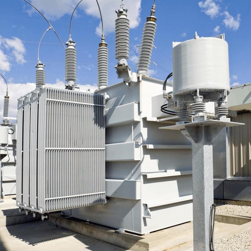
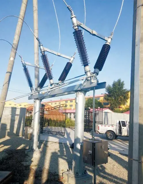
A certain 110 kV substation employs GW16B/17B-252 type high-voltage disconnectors. Their technical specifications are listed in Table 1. This disconnector is a three-pole outdoor high-voltage device designed for no-load switching operations in 110 kV substations, providing electrical isolation between equipment under maintenance and energized circuits.
| Item | Value | |
| Rated Voltage / kV | 110 | |
| Rated Frequency / Hz | 50 | |
| Rated Current / A | 2 000/3 000/4 000 | |
| Duration of Dynamic Stable Current for Main Knife and Ground Knife / s | 3.5 |
|
| Dynamic Stable Current for Main Knife and Ground Knife / kA | 100/130/160 | |
| Power Frequency Withstand Voltage (Effective Value) / kV | To Ground | 230 |
| Fracture | 305 | |
| Lightning Impulse Withstand Voltage (Peak Value) / kV | To Ground | 590 |
| Fracture | 690 | |
| Mechanical Life / Times | 10000 |
|
| Insulation Creepage Distance (Class III) / mm | 6700 | |
| Torsion Strength of Each Rotating Porcelain Insulator / (N·m) | 2200 | |
| Torsion Strength of Upper Section Supporting Porcelain Insulator / N | 6100 | |
| Torsion Strength of Lower Section Supporting Porcelain Insulator / N | 12700 | |
Key features of this disconnector include a compact structure, high oxidation resistance, stable operation, and strong seismic performance. Its mechanical contact system adopts a simple single-arm flexure design, with transmission components housed inside the conductive tube to shield them from external environmental interference. Inside the conductive tube are installed a pair of balancing springs and a set of clamping springs: the former ensures reliable mechanical balance during opening and closing operations, while the latter provides sufficient contact pressure for secure clamping.
Since disconnectors are typically installed outdoors, they are subject to external influences such as wind and seismic activity. To enhance operational reliability, a latching mechanism is integrated into the disconnector body to ensure stable and secure closing. Both the disconnector and its grounding switch use aluminum alloy conductive tubes, with silver- or gold-plated moving and stationary contacts to guarantee wear resistance, mechanical robustness, and electrical stability at rotating joints.
The grounding switch features a single-arm swing structure. During closing, the movable contact first rotates and then moves vertically upward to engage the stationary contact, preventing contact bounce or rebound. This design ensures reliable closure and consistent dynamic and thermal stability under rated short-circuit current conditions.
The operating process of a disconnector consists of two main actions: bending action and clamping action.
Guided by a horizontal rotary mechanism, a pair of gears mounted on the rotating porcelain insulator drives two sets of four-bar linkages to perform planar motion. Under this drive, the lower conductive tube rotates forward to close (close operation) or backward to open (open operation). The hinged actuating rod at the top of the operating screw thus generates axial displacement relative to the lower conductive tube.
The upper end of this hinged actuating rod is connected to a gear-chain assembly. As the rod moves, it rotates the chain, which in turn drives the gear. This causes the upper conductive tube—fixed to the gear shaft—to move relative to the lower conductive tube, either straightening (closing) or bending (opening).
Simultaneously, as the hinged actuating rod undergoes axial movement, the balancing springs inside the conductive tube continuously store and release energy. This effectively counterbalances the heavy braking torque, ensuring smooth and stable operation throughout the entire switching cycle.
As the disconnector moves from the open position toward the closed position and approaches full alignment (i.e., near-straight configuration), the gear engages with an inclined plane on the gearbox and continues sliding along it. At this point, under the reactive force of the return spring, the hinged actuating rod—linked to the gear-chain—moves forward.
This forward motion is transmitted through the moving contact assembly, where a push rod converts linear movement into a clamping action of the contact fingers. Once the stationary contact rod is securely gripped, the gear slides slightly upward along the inclined plane to achieve full mechanical closure.
At this stage, the clamping spring inside the conductive tube is further compressed and exerts force on the push rod, ensuring a stable driving force that maintains consistent and reliable contact pressure between the contact fingers and the stationary rod.
During the opening operation, the gear continues moving outward along the inclined plane until it disengages completely. The return spring then pulls the push rod, causing the contact fingers to open in a “V” shape, thereby breaking the electrical connection.
In a certain year, during a switching operation at the 110 kV substation, one high-voltage disconnector failed to open. A comprehensive inspection was immediately conducted on the grounding system, main conductive system, mechanical interlock, upper/lower conductive tubes, and the motorized operating mechanism. The investigation revealed that the transmission gear inside the motor mechanism box was damaged, and components such as shaft pins and joints were fractured. Operation and maintenance personnel reported the defect, and corrective measures were implemented according to the annual maintenance schedule.
(1) Upgraded Auxiliary Components
Shaft pins and joints were replaced with high-quality stainless steel to prevent corrosion during long-term operation. Graphite-impregnated and composite bushings—resistant to corrosion and with low friction coefficients—were adopted to enhance transmission efficiency. All exposed ferrous parts were hot-dip galvanized, significantly improving anti-corrosion performance. Field experience confirms that hot-dip galvanizing is well-suited for outdoor applications.
(2) Enhanced Motorized Operating Mechanism
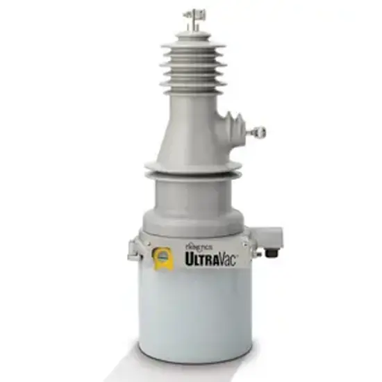
The original CJ7A motor mechanism was replaced with the newer CJ11 model. A photograph of the upgraded CJ11 mechanism is shown in Figure 1.
(3) Advanced Auxiliary Switch Design
The auxiliary switch is a critical secondary component that provides open/close status signals. Failure could result in incorrect signaling and operational malfunction. The new design employs an internationally advanced cam-driven micro-switch mechanism, ensuring reliable switching, smooth rotation, and immunity to failure during open/close transitions.
(4) Motor Control Protection
After completion of an open or close operation, the motor power is first cut off by the auxiliary switch. If the auxiliary switch fails, terminal limit switches on both open and close sides disconnect the motor. Should these also fail, mechanical stoppers on both sides activate a thermal relay to cut power. This three-tier protection system reliably stops the motor after each operation, preventing uncontrolled motion and potential mechanical damage.
(5) Mechanical Transmission System
A worm-gear linkage system is used. The worm gear, linkages, and other reduction components are precision-machined and sealed within an aluminum alloy housing. This design ensures smooth operation, low noise, and no impact shocks.
(6) Secondary Control System
The control panel features a rational and aesthetically pleasing layout with a hinged door structure, facilitating wiring and on-site maintenance while ensuring safe and reliable secondary system operation.
(7) Enclosure Sealing
The mechanism enclosure uses air-cushion sealing on the door. Both the door and top cover are made of 2.5 mm thick stainless steel, while the main body uses 2 mm thick stainless steel, providing excellent resistance to wind, sand, and corrosion.
Based on years of operational experience and fault analysis of disconnector motor mechanisms at this 110 kV substation, the original mechanism was upgraded to the CJ11 model developed by Pinggao Group—a newly designed, independently developed worm-gear-type motorized operating mechanism. This improved design overcomes previous shortcomings in both engineering and manufacturing, offering high operational reliability, smooth motion, high transmission efficiency, no inertial impact, low noise, strong interchangeability, and an attractive appearance.
In addition to local and remote electric operation, the CJ11 mechanism also supports manual operation. Practical testing under rated load conditions has demonstrated its capability to perform over 10,000 mechanical operations reliably.