I. CLAIMS
A sealing structure for lead wires of contacts in an oil-filled SF6 gas density relay, characterized by comprising a relay housing (1) and a terminal base (2); the terminal base (2) comprising a terminal base housing (3), a terminal base seat (4), and conductive pins (5); the terminal base seat (4) being disposed inside the terminal base housing (3), the terminal base housing (3) being welded onto the surface of the relay housing (1); a central through-hole (6) being provided at the center of the surface of the terminal base seat (4), and a plurality of fixing holes (7) being arranged circumferentially around the surface; the conductive pins (5) being fixed within the fixing holes (7) via glass frit (8), the glass frit (8) sealing at least radially the gap between each fixing hole (7) and the corresponding conductive pin (5).
The sealing structure according to claim 1, characterized in that the number of the fixing holes (7) is six.
The sealing structure according to claim 1, characterized in that the glass frit (8) is formed by sintering glass to bond the terminal base seat (4) and the conductive pins (5).
The sealing structure according to claim 1, characterized in that one end of each conductive pin (5) is located inside the terminal base housing (3), while the other end is located outside the terminal base housing (3).
The sealing structure according to claim 4, characterized in that the end of the conductive pin (5) located inside the terminal base housing (3) is electrically connected to the contact of the SF6 gas density relay.
The sealing structure according to claim 1, characterized in that the terminal base seat (4) is made of stainless steel.
The sealing structure according to claim 1, characterized in that the conductive pins (5) are made of Kovar alloy.
II. DESCRIPTION
1. Technical Field
[0001] The present utility model relates to an SF6 gas density relay, particularly to a sealing structure for lead wires of contacts in an oil-filled SF6 gas density relay.
2. Background Art
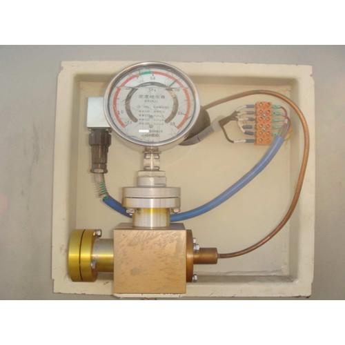
[0002] In industrial applications and daily operations, many instruments with liquid- or gas-filled housings are widely used, such as liquid-filled electrical contact gauges (e.g., anti-vibration oil-filled pressure gauges) used in chemical, power, metallurgy, and water supply industries, as well as oil-filled electrical contact pressure gauges, absolute-pressure-type SF6 gas density relays, and oil-filled SF6 gas density relays used in power systems and factories. For these field-installed instruments, the sealing of contact lead-out wires is commonly achieved by either “embedding metal components in plastic” or “adhesive sealing.” However, these methods provide relatively poor sealing performance. Over time and under temperature variations, leakage of internal liquid or gas from the housing may occur, severely affecting the safe and reliable operation of the system. Replacing such instruments incurs significant costs. Moreover, since the arc-quenching and insulation media of SF6 electrical equipment depend on SF6 gas, any gas leakage compromises their safe and reliable operation.
[0003] Currently, relay contacts are mainly classified into two types: electrical contact type and micro-switch type. Electrical contact type density relays usually require filling with anti-vibration silicone oil, and in environments with severe vibration, even micro-switch type density relays may need to be oil-filled. However, existing oil-filled density relays on the market often suffer from oil leakage due to inadequate sealing of the contact lead-out wires, causing losses to users.
[0004] Furthermore, conventional junction boxes are mostly constructed by embedding copper cores in plastic. Due to the different thermal expansion coefficients between plastic and metal, cracks tend to form after prolonged use, leading to failure of the sealing performance.
3. Summary of the Utility Model
[0005] The purpose of the present utility model is to overcome the deficiencies of the prior art by providing a sealing structure for the contact lead-out wires of an oil-filled SF6 gas density relay.
[0006] To solve the above technical problem, the utility model adopts the following technical solution: A sealing structure for contact lead-out wires of an oil-filled SF6 gas density relay comprises a relay housing and a terminal base; the terminal base comprising a terminal base housing, a terminal base seat, and conductive pins; the terminal base seat being disposed inside the terminal base housing, the terminal base housing being welded onto the surface of the relay housing; a central through-hole being provided at the center of the surface of the terminal base seat, and multiple fixing holes being arranged circumferentially on the surface; the conductive pins being fixed in the fixing holes via glass frit, the glass frit sealing at least radially the gap between the fixing holes and the conductive pins.
[0007] Preferably, the number of fixing holes is six.
[0008] Preferably, the glass frit is formed by sintering glass to bond the terminal base seat and the conductive pins.
[0009] Preferably, one end of each conductive pin is located inside the terminal base housing, while the other end is located outside the terminal base housing.
[0010] Preferably, the end of the conductive pin located inside the terminal base housing is electrically connected to the contact of the oil-filled SF6 gas density relay.
[0011] Preferably, the terminal base seat is made of stainless steel.
[0012] Preferably, the conductive pins are made of Kovar alloy.
[0013] Beneficial effects of the utility model compared with the prior art: The sealing structure provided by the present utility model employs a dual-sealing design—“welding the terminal base housing to the relay housing” combined with “bonding the terminal base seat and conductive pins via glass frit”—achieving complete sealing. This significantly enhances the overall sealing performance of the relay housing, effectively preventing oil leakage and fully meeting the operational requirements of oil-filled SF6 gas density relays.
III. BRIEF DESCRIPTION OF THE DRAWINGS
[0014] Figure 1: Overall schematic view of the sealing structure of the present utility model;
[0015] Figure 2: Front view of the sealing structure of the present utility model;
[0016] Figure 3: Cross-sectional view of the sealing structure of the present utility model;
[0017] Figure 4: Top view of the sealing structure of the present utility model.
[0018] Reference numerals in the figures:
1 Relay housing
2 Terminal base
3 Terminal base housing
4 Terminal base seat
5 Conductive pin
6 Through-hole
7 Fixing hole
8 Glass frit
IV. DETAILED DESCRIPTION
[0022] The present utility model will be further described below with reference to Figures 1–4 and embodiments.
[0023] The sealing structure for contact lead-out wires of an oil-filled SF6 gas density relay provided by the present utility model primarily consists of a relay housing (1) and a terminal base (2). The terminal base (2) includes a terminal base housing (3), a terminal base seat (4), and conductive pins (5). The terminal base seat (4) is internally housed within the terminal base housing (3), and the terminal base housing (3) is welded to the surface of the relay housing (1), thereby ensuring the sealing between the terminal base (2) and the relay housing (1).
[0024] Two key structural features are designed on the surface of the terminal base seat (4): a central through-hole (6) at the center, and six fixing holes (7) evenly distributed around the circumference. The conductive pins (5) are fixed within the fixing holes (7) using glass frit (8), which completely seals the gaps between the fixing holes (7) and the conductive pins (5) at least in the radial direction. The glass frit (8) is formed by a glass sintering process, enabling the glass to tightly bond with both the terminal base seat (4) and the conductive pins (5), thereby further enhancing the internal sealing performance of the terminal base (2).
[0025] The conductive pins (5) adopt a "through-wall" design: one end extends inside the terminal base housing (3) and is connected via wire to the internal contact of the relay; the other end extends outside the terminal base housing (3) for connection to external equipment via wiring. This design enables external devices to monitor the on/off status of the internal contacts of the relay in real time. Additionally, the terminal base seat (4) is made of stainless steel, and the conductive pins (5) are made of Kovar alloy, ensuring compatibility in terms of mechanical strength and electrical conductivity.
[0026] It should be noted that the scope of protection of the present utility model is defined by the claims. Any modifications or improvements made by those skilled in the art without departing from the spirit and scope of the utility model shall fall within the protective scope of the present utility model.


