On-Site Testing of SF6 Gas Density Relays: Relevant Issues

Introduction
SF6 gas is widely used as an insulating and arc-quenching medium in high-voltage and extra-high-voltage electrical equipment due to its excellent insulation, arc-extinguishing properties, and chemical stability. The insulation strength and arc-quenching capability of electrical equipment depend on the density of SF6 gas. A decrease in SF6 gas density can lead to two main hazards:
Reduced dielectric strength of the equipment;
Decreased interrupting capacity of circuit breakers.
Additionally, gas leakage often leads to moisture ingress, increasing the moisture content of SF6 gas and further degrading insulation performance. Therefore, monitoring the density of SF6 gas is essential for ensuring safe equipment operation.
An SF6 gas density relay (also known as a density monitor, controller, or density gauge) is installed on SF6 electrical equipment to reflect changes in internal gas density. It detects pressure variations to indicate density changes, issuing an alarm signal when density drops to a preset alarm level, and locking out switching operations if it further decreases to a lockout level. Given that its performance directly affects equipment safety, regular testing of its reliability and accuracy is crucial.
1. Types and Operating Principles of SF6 Gas Density Relays
1.1 Mechanical Gas Density Relays
Mechanical relays can be classified by structure into bellows-type and bourdon-tube-type, and by function into those with pressure display and without. Both types use temperature compensation to monitor gas density.
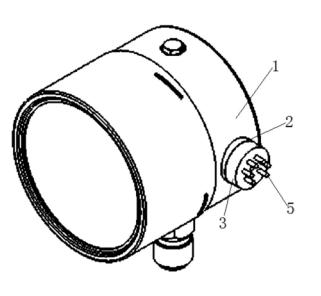
Taking the typical bellows-type as an example (see Figure 1):
A pre-charged chamber is filled with SF6 gas at the same pressure as the monitored chamber;
A metal bellows is connected to the monitored chamber;
When a leak occurs, the internal pressure in the bellows decreases, creating a pressure differential that compresses the bellows.This movement actuates a microswitch via a mechanical linkage,triggering an alarm or lockout signal.
Since the pre-charged chamber is in the same environment, temperature changes affect both sides equally, enabling automatic temperature compensation.

Figure 1. Principle of Mechanical Gas Density Relay
(Note: 4—microswitch; 3—bimetal strip; 2—metal bellows; 1—pre-charged chamber)
1.2 Digital Gas Density Relays
These relays exploit the strong electronegativity of SF6 molecules. An alpha particle source in an ionization chamber ionizes the gas, and under an applied DC electric field, an ion current is formed. This current is proportional to the gas density. As density decreases, the output current decreases, allowing real-time monitoring.
Advantages of digital density relays include:
Direct digital display of pressure, equivalent pressure at 20°C, and equipment temperature;
Compatibility with computer systems for online monitoring;
Ability to plot leakage trend curves, supporting condition-based maintenance;
Full-scale measurement without range switching, with field-adjustable parameters;
Output of gas-refill alarm and under-pressure lockout contact signals.

Figure 2. Principle of Digital Gas Density Relay
(Note: Alpha particles in the ionization chamber ionize SF6 gas; electrons migrate to the anode, positive ions return to the emitter, generating a current that is amplified and output)
2. Necessity of On-Site Testing of Density Relays
Density relays can be tested either on-site or in a laboratory. While laboratory testing offers higher precision, it presents several drawbacks:
Dismantling breaks the original seal, making reassembly and sealing difficult to guarantee;
Precision instruments may lose calibration due to transportation shocks;
Tight maintenance schedules make disassembly and reassembly time-consuming.
Therefore, on-site testing is recommended when feasible, as it is more efficient and safer.
3. Instruments Used for On-Site Testing
Since SF6 electrical equipment must not be contaminated with oil or other gases, only SF6 gas can be used as the test medium. An ideal calibration device should have:
An integrated SF6 gas cylinder;
Adjustable pressure;
Automatic temperature compensation and conversion.
This article introduces the JMD-1A SF6 Gas Density Relay Calibration Unit, which features:
Built-in SF6 cylinder and pressure regulation system;
Isolates the equipment’s gas circuit during testing, using its own gas supply;
Automatically converts measured values to standard pressure at 20°C;
Requires annual factory recalibration to ensure accuracy;
Accuracy class 0.5, meeting the requirement that “standard instrument error shall not exceed one-third of the tested instrument’s error” (tested relays are typically below class 1.5), fully satisfying on-site requirements.
4. Testing Content for Gas Density Relays
4.1 Testing Standards and Frequency
According to GB50150-1991 and DL/T596-1996:
New equipment must undergo density relay testing before commissioning;
In-service equipment should be tested every 1–3 years, or after major maintenance or when necessary;
Action values must comply with manufacturer’s technical specifications;
Pressure gauge indication error and hysteresis must be within allowable limits for the specified accuracy class.
4.2 Test Items
Main test items include:
Alarm (gas refill) activation pressure;
Lockout activation pressure;
Lockout return pressure;
Alarm return pressure;
If equipped with a pressure gauge, its indication must also be tested.
Pressure gauge testing requirements:
At least 5 test points evenly distributed across the range;
Two full cycles of pressurization and depressurization;
Pressure applied slowly and steadily, with readings taken at each point;
The maximum indication error from the two cycles is taken as the final result.
Action value requirements:
Must comply with manufacturer’s specifications;
The difference between activation and return pressure should be less than 0.02 MPa;
All pressure values must be converted to standard values at 20°C;
Record ambient temperature, measured pressure, and converted 20°C pressure.
5. Connection Methods Between Density Relay and Equipment
There are four common connection types:
With Isolation Valve
A valve (FA) is installed between the relay and equipment. During testing, close FA, connect the test head, then open FB to begin testing.With Check Valve
After removing the relay, the check valve automatically seals the equipment side, allowing direct connection of the test device to the external port.With Check Valve + Plunger Bolt (see Figure 3)
No disassembly required. Unscrew the plunger bolt at W2; the check valve F1 automatically isolates the gas path, allowing direct connection of the test head.

Figure 3. Schematic of Density Relay with Check Valve and Plunger Bolt
(Labels: B1—density relay; W1—gas charging port; W2—test port; MA—pressure gauge; F1—check valve)
Direct Connection Without Isolation
This is an unreasonable design. If the relay fails, it cannot be replaced or tested online and must wait until major overhaul. It is recommended to install isolation valves during overhaul for future maintenance.
Conclusion: The first three connection types allow on-site testing; the fourth does not.
6. Precautions for On-Site Calibration
Power-Off Operation: Testing must be conducted with the equipment de-energized. Disconnect control power and isolate alarm/lockout contacts at the terminal block to prevent unintended secondary circuit operation.
Confirm Connection Type: Connection structures vary among equipment. Confirm the type before disassembly to prevent misoperation and gas leakage.
Restore Isolation Valves: After testing, ensure all isolation valves are restored to their correct positions and verified.
Clean Connectors: Clean all piping connectors before and after testing. Flush with a small amount of SF6 gas if necessary to prevent contamination or moisture ingress.
Sealing Protection: Protect sealing surfaces, replace with new gaskets, and perform leak detection after reassembly.
Pressure Unit Conversion: The JMD-1A tester displays gauge pressure. If the relay uses absolute pressure (e.g., ABB LTB145D circuit breaker), convert units before comparison.
7. Conclusion
The SF6 gas density relay is a critical component ensuring the safe operation of SF6 electrical equipment. Its operational performance directly impacts system reliability. Therefore, regular on-site testing must be conducted in accordance with relevant regulations to ensure accuracy and reliability. During testing, strict adherence to prescribed test cycles, procedures, and precautions is essential to eliminate safety hazards and prevent erroneous conclusions.