Pêşnûmara
Gazî SF6 bi biniyên her û dengdariyekî yên wekheviyên zorî û çend zorî yên elektrîkî di hatîya ve werin bikarber kirin vegere ku hewlêkariyekî û xwastîkirina her û nîstîna her û rastîn û stabîlîn kîmyavî. Dengdariyekî û xwastîkirina cihedanên elektrîkî parastîn li ser dergeha SF6 gas. Dargûzekeke dergeha SF6 gas dikarin du çendîn pirsgirêkî bibin:
Dergeha her û nîstîna cihedan;
Xwastîkirina berhatakeyan.
Lêm, digerandina gaz dikare werekîne binekirina su, ku dergeha su ya SF6 gas biguhere û her û nîstîna binekirine. Buna, pîvan dergeha SF6 gas bibe tevistîne ji bo taybetkirina karbikariyekî cihedan.
Relâyê dergeha SF6 gas (di navbera din jî relâyê dergeha, kontroler, an pîvaniya dergeha) li ser cihedanên elektrîkî SF6 gas hatîn bike girîngkirin bi biniyekî da ku guherandinên dergeha gazê navenda navendî bibin. Relâyê vê guherandinên dergeha bi biniyekî da ku ferqeyên demgerî bibin, belavdarî werin bi biniyekî da ku dergeha be dergeha alarmê bide, u ewerina qopêrê dibike bi biniyekî da ku dergeha yê wêra bide. Ji ber ku performansa wê direkî dereceyê cihedan, testkirina mînawayê u rastîna wê heye tevistî.
1. Cûrekan û Prinsîpên Karanîna Relâyên Dergeha Gazî SF6
1.1 Relâyên Mekanîkî Dergeha Gazî
Relâyên mekanîkî di cûrekî de bi rêzikî bellows-type û bourdon-tube-type, û di fonksiyonî de bi rêzikî piştgirî demgerî bibin. Her du rêzikî wan bi biniyekî da ku dergeha gazê piştgirî bin.
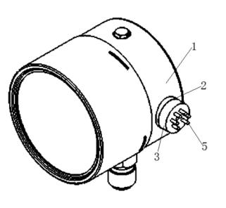
Li gorî rêzikî bellows-type (ji Figûra 1):
Oda pre-charged bi SF6 gas ji demgerî yê nasnameyê bi serdemegî yê nasnameyê bibin;
Bellows metalî bi serdemegî yê nasnameyê bibin;
Ji bo digerandina, demegerî yê navendî di bellows de dargûzek, ku ferqeyên demgerî bibin ku bellows kompress bide. Vê hilanîn bi biniyekî da ku mikroswitch bi lînkî mekanîkî aktive bide, ku belavdarî u ewerina qopêrê dibike.
Ji ber ku oda pre-charged li ser dema yekemî, guherandinên demgerî di her du tarafan de bi biniyekî da ku piştgirî demgerî automatîk bibin.

Figûra 1. Prinsîpê Relâyê Dergeha Gazî Mekanîkî
(Têkevin: 4—mikroswitch; 3—bimetal strip; 2—bellows metalî; 1—oda pre-charged)
1.2 Relâyên Digital Dergeha Gazî
Relâyên digital wan bi biniyekî da ku electronegativityya zorî SF6 molecules bikar bine. Îonizasyona gaz bi alpha particle source di ionization chamber de îoniz bide, u di demgerî DC electric field de îon current form bide. Ev current proporsional bi dergeha gaz. Jî dergeha bide, output current bide, ku pîvan monitorî şopîn bide.
Avantajên relâyên digital dergeha:
Pîvan digital pressure, equivalent pressure at 20°C, u temperature equipment;
Kompatibîl bi computer systems ji bo online monitoring;
Ability to plot leakage trend curves, supporting condition-based maintenance;
Full-scale measurement without range switching, with field-adjustable parameters;
Output of gas-refill alarm and under-pressure lockout contact signals.

Figûra 2. Prinsîpê Relâyê Dergeha Gazî Digital
(Têkevin: Alpha particles in the ionization chamber ionize SF6 gas; electrons migrate to the anode, positive ions return to the emitter, generating a current that is amplified and output)
2. Piştgirî Testkirina Relâyên Dergeha Serhatî
Relâyên dergeha bi biniyekî da ku serhatî test bide, an di laboratorî de test bide. Ji ber ku testkirina laboratorî precision zorî bide, vê pirsgirêkî yên çendîn bide:
Dismantling breaks the original seal, making reassembly and sealing difficult to guarantee;
Precision instruments may lose calibration due to transportation shocks;
Tight maintenance schedules make disassembly and reassembly time-consuming.
Buna, testkirina serhatî piştgirî bide ji bo êk bêt, ji ber ku efîsîyan u taybet bibe.
3. Instruments Used for On-Site Testing
Since SF6 electrical equipment must not be contaminated with oil or other gases, only SF6 gas can be used as the test medium. An ideal calibration device should have:
An integrated SF6 gas cylinder;
Adjustable pressure;
Automatic temperature compensation and conversion.
This article introduces the JMD-1A SF6 Gas Density Relay Calibration Unit, which features:
Built-in SF6 cylinder and pressure regulation system;
Isolates the equipment’s gas circuit during testing, using its own gas supply;
Automatically converts measured values to standard pressure at 20°C;
Requires annual factory recalibration to ensure accuracy;
Accuracy class 0.5, meeting the requirement that “standard instrument error shall not exceed one-third of the tested instrument’s error” (tested relays are typically below class 1.5), fully satisfying on-site requirements.
4. Testing Content for Gas Density Relays
4.1 Testing Standards and Frequency
According to GB50150-1991 and DL/T596-1996:
New equipment must undergo density relay testing before commissioning;
In-service equipment should be tested every 1–3 years, or after major maintenance or when necessary;
Action values must comply with manufacturer’s technical specifications;
Pressure gauge indication error and hysteresis must be within allowable limits for the specified accuracy class.
4.2 Test Items
Main test items include:
Alarm (gas refill) activation pressure;
Lockout activation pressure;
Lockout return pressure;
Alarm return pressure;
If equipped with a pressure gauge, its indication must also be tested.
Pressure gauge testing requirements:
At least 5 test points evenly distributed across the range;
Two full cycles of pressurization and depressurization;
Pressure applied slowly and steadily, with readings taken at each point;
The maximum indication error from the two cycles is taken as the final result.
Action value requirements:
Must comply with manufacturer’s specifications;
The difference between activation and return pressure should be less than 0.02 MPa;
All pressure values must be converted to standard values at 20°C;
Record ambient temperature, measured pressure, and converted 20°C pressure.
5. Connection Methods Between Density Relay and Equipment
There are four common connection types:
With Isolation Valve
A valve (FA) is installed between the relay and equipment. During testing, close FA, connect the test head, then open FB to begin testing.
With Check Valve
After removing the relay, the check valve automatically seals the equipment side, allowing direct connection of the test device to the external port.
With Check Valve + Plunger Bolt (see Figure 3)
No disassembly required. Unscrew the plunger bolt at W2; the check valve F1 automatically isolates the gas path, allowing direct connection of the test head.

Figure 3. Schematic of Density Relay with Check Valve and Plunger Bolt
(Labels: B1—density relay; W1—gas charging port; W2—test port; MA—pressure gauge; F1—check valve)
Direct Connection Without Isolation
This is an unreasonable design. If the relay fails, it cannot be replaced or tested online and must wait until major overhaul. It is recommended to install isolation valves during overhaul for future maintenance.
Conclusion: The first three connection types allow on-site testing; the fourth does not.
6. Precautions for On-Site Calibration
Power-Off Operation: Testing must be conducted with the equipment de-energized. Disconnect control power and isolate alarm/lockout contacts at the terminal block to prevent unintended secondary circuit operation.
Confirm Connection Type: Connection structures vary among equipment. Confirm the type before disassembly to prevent misoperation and gas leakage.
Restore Isolation Valves: After testing, ensure all isolation valves are restored to their correct positions and verified.
Clean Connectors: Clean all piping connectors before and after testing. Flush with a small amount of SF6 gas if necessary to prevent contamination or moisture ingress.
Sealing Protection: Protect sealing surfaces, replace with new gaskets, and perform leak detection after reassembly.
Pressure Unit Conversion: The JMD-1A tester displays gauge pressure. If the relay uses absolute pressure (e.g., ABB LTB145D circuit breaker), convert units before comparison.
7. Conclusion
The SF6 gas density relay is a critical component ensuring the safe operation of SF6 electrical equipment. Its operational performance directly impacts system reliability. Therefore, regular on-site testing must be conducted in accordance with relevant regulations to ensure accuracy and reliability. During testing, strict adherence to prescribed test cycles, procedures, and precautions is essential to eliminate safety hazards and prevent erroneous conclusions.