
1 Yadda a Gargajiya
Bayanai masu kula (wanda ke da lokacin da za suka dace/za suka rufe, hikima, fari na zama, karshen kayayyaki, asynchrony ta uku, lokacin da za suka sauke, kamar haka) sun fi yawa don maimakon 10 kV indoor vacuum circuit breakers, wanda ke taimakawa da tashar rawa da kyau da kuma kwallonsa. Mafi girman maimakon sun amfani da metoda na linear sensor ta moving-contact, domin ya bayyana nasara a kan yadda ake yi bayanai da motion curves mai kyau bayan linear transmission rod da moving contacts.
Don in ba da shiga bayanai, mafi girman maimakon suna iya sanya screw holes da test racks. Amma, propulsion chassis ta switchgear yana haifar da karamin karamin rod bottom, wanda ke nufin cewa an bukatar rack-based sensor installation—wanda ba da shi ko ba da shi ba a kan ground bayan da shi bai samu tabbataccen abubuwa, wanda ke ya haifar da linear sensor handling.Idan an amfani da rotation sensors (wadanda ke bukatar travel parameter input), su ne suna iya zama workarounds, amma irin mafi girman breakers suna da wurin spindle-end holes don coupling. Saboda haka, wani sabbin transition joint ya ba da shi don in ba da shiga reliable rotation-sensor connection zuwa spindle, wanda ke tsarkar installation.
2 Teknologi Na Zamantakewa Transition Joint
2.1 Tsarin Kirkiro
Don in ba da shiga reliable connection bayan rotation sensor da end of the main shaft, yawancin masu muhimmanci masu hanyar kirkiro suna bukata:
A nan da transition joint ya faru, ya kamata a duba cewa center line ta crank arm main shaft ta circuit breaker ce ta sama da axial center line ta sensor coupling, yana nufin cewa za a duba coaxial center.
A nan da transition joint ya faru, rotation angle ya kamata ta sama da crank arm main shaft ta circuit breaker a lokacin movement, kuma ba za a samu rotation additional ba wajen rotation ta main shaft, yana nufin cewa za a duba external rotation ta main shaft.
A nan da transition joint ya faru, ba za a samu axial movement ba. Wannan shine abin da ya fi muhimmanci a nan da suka shiga problem, yana nufin cewa za a duba axial movement.
2.2 Solutions
(1) Machining accuracy tolerance ta outer circle ta crank arm main shaft ta circuit breaker ta kontrolle a kan 0.01 mm. Saboda haka, outer circle ta main shaft zai iya amfani da shi don in duba center line ta transition joint, wanda ke ya bayyana coaxial center da kyau.
(2) Saboda bukatar assembling crank arm, crank arm main shaft ta circuit breaker ta processed da keyways ta fadi 8 mm ko 10 mm (da wasu variations), kuma error ta kontrolle a kan 0.01 mm, wanda ke ya sama da outer diameter ta 8.8-grade M8 da M10 high-strength bolts, wanda ke ya bayyana external rotation ta main shaft da kyau.
(3) A nan da transition joint ya faru, ba da abubuwa da take da large-scale axial movement ko significant axial force. Fixing transition joint zuwa circuit breaker's crankshaft spindle da circular thin-sheet strong magnet zai iya counteract axial displacement ta sensor da take da operational vibrations ta circuit breaker a lokacin measurement, wanda ke ya bayyana axial movement da kyau.
Ta haka, tushen da ake amfani da structural characteristics ta circuit breaker, muna gina axial magnetic-attraction fixed-type transition joint don speed-measuring rotation sensor ta vacuum circuit breaker, wanda ke amfani da outer circle ta crank arm main shaft don in duba axis line.
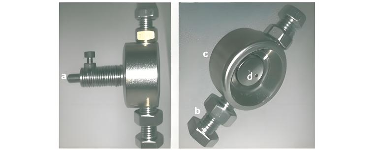
Daga design scheme, ana zaba Q235A iron rod ta fadi 60 mm da tsakiyar 40 mm don blank, wanda ke machined zuwa circular full-enclosed structure a kan lathe. Inner diameter ta front end ta processed zuwa 32 mm da dimensional error ta kontrolle a kan 0.01 mm don in duba precise fitting zuwa spindle end; tail ta machined zuwa circular rod ta tsakiyar 12 mm don sensor connection. Biyu circular holes ta inner diameter ta 8 mm ta drill a opposite sides ta body da tapped don fit installation ta M8 da M10 high-strength bolts.
Strong magnetic sheet ta tsakiyar 16 mm da tsabta 2 mm ta sai. Hole ta drill a tail circular rod ta body don in machine transition connecting rod don coupling zuwa shaft coupling. Finished structure ta shahara a Figure 1:
3 Tattalin Aiki
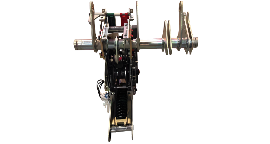
The overall assembly of the rotation sensor was completed using the transition joint, and the field test effect is shown in Figure 3. After the design and manufacture of the rotation sensor transition joint were completed, a VS1-12 indoor vacuum circuit breaker with a threaded hole for the rotation sensor transition joint at the shaft end was selected. Using the same circuit breaker mechanical characteristics tester, test comparisons were carried out respectively with the original transition joint and the transition joint for the installation of the rotation sensor with a lead screw.
When compared with the original transition joint, the difference in the three sets of self-inspection measurement data was within 2 decimal places (the actual measurement results retain 1 decimal place), indicating that the stability of this transition joint is good; when compared with the transition joint for lead screw installation, the difference in the three sets of measurement data was also within 2 decimal places (the actual measurement retains 1 decimal place), indicating that the measurement accuracy of its design meets the requirements.
In actual use, the wear of the ends of the M8 or M10 high-strength bolts that fit with the keyway is relatively prominent. Therefore, generally, 2-3 spare bolts are provided for each. If there is even a slight rotational clearance, they are replaced immediately. Usually, new bolts need to be replaced after testing about 30 units.


