Handling 35kV Substation Fault Tripping

Analysis and Handling of Fault Tripping in 35kV Substation Operation
1. Analysis of Tripping Faults
1.1 Line-Related Tripping Faults
In power systems, the coverage area is extensive. To meet power supply demands, numerous transmission lines must be installed—posing significant management challenges. Especially for special-purpose lines, installations are often located in remote areas such as suburbs to minimize impact on residential life. However, these remote areas have complex environments, making line maintenance and inspection difficult. Poor inspection, repair, and management practices often result in undetected line defects, increasing the likelihood of substation faults.
Moreover, when lines pass through forested areas, external factors such as tree contact and lightning strikes can easily trigger tripping faults—and even cause major fires, posing serious threats to power safety.
1.2 Low-Voltage Side Main Transformer Switch Tripping
This type of tripping is typically caused by one of three conditions: incorrect breaker operation, over-tripping (cascade tripping), or busbar faults. The exact cause can only be determined after inspecting primary and secondary equipment.
If only the low-voltage overcurrent protection of the main transformer operates, switch failure or misoperation can be ruled out. To distinguish between over-tripping and busbar faults, a comprehensive equipment inspection is required.
For secondary equipment, focus on protective relays and signaling.
For primary equipment, inspect all devices within the overcurrent protection zone.
If no protection trip signal ("drop card" signal) is present, determine whether the fault was due to a failed protection signal or hidden two-point grounding causing the trip.
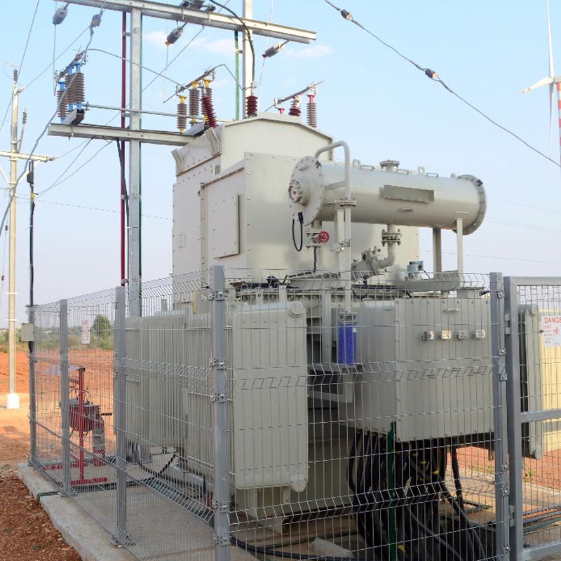
1.3 Three-Side Main Transformer Switch Tripping
Common causes of three-side tripping include:
Internal transformer faults
Low-voltage busbar faults
Short circuits on the low-voltage busbar
To prevent such faults, substation technicians should conduct regular inspections of the three-side breakers and implement gas (Buchholz) protection to safeguard the transformer.

2. Handling Techniques for Tripping Faults
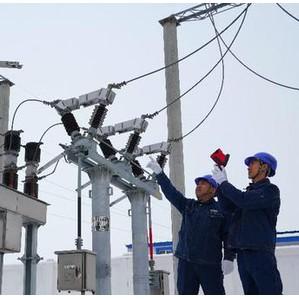
2.1 Handling Line Tripping Faults
When a 35kV substation experiences a line trip, an immediate inspection should be conducted based on the protection action taken. The inspection area should be defined between the line outlet and the line CT side, using the CT circuit diagram as a reference.
If no fault is found in this zone, proceed to check the tripped breaker, following this sequence:
Breaker position indicator
Three-phase linkage arms
Arc suppression coil
Inspection focus varies by breaker type:
Spring-operated breakers: Check spring energy storage.
Electromagnetic breakers: Inspect fuse and power contact conditions.
Only after fault clearance should the line be re-energized.
2.2 Handling Low-Voltage Side Main Transformer Switch Tripping
After a trip:
If only low-side overcurrent protection operated without a trip signal, inspect the secondary circuit: check for blown fuses or missing protection relay links (pressure plates).
For primary equipment, inspect all devices connected to the low-voltage bus and the line outlet.
If both line protection and overcurrent protection operated, but the line breaker did not trip, it indicates a line fault. Conduct a line patrol from the outlet to the fault point. The solution is simple: isolate the fault by opening disconnectors on both sides of the breaker, restoring power to healthy equipment.
If the main transformer trips without any protection signal, the cause may be:
Protection failure (failure to operate)
Two-point grounding
Breaker mechanical failure
In such cases, the transformer protection system may still generate a signal indicating relay failure. To handle this:
Open all breakers on the bus.
Attempt to re-energize the low-voltage side of the transformer.
Gradually restore power to other feeders.
2.3 Handling Three-Side Main Transformer Tripping
To determine if a fault involves three-side tripping, inspect protection signals and primary equipment:
If Buchholz (gas) protection operates, the fault is likely in the transformer interior or secondary circuit, not in the external system. Check for:
Oil spraying from the conservator tank or breather
Grounding or short circuits in the secondary circuit
Transformer deformation or fire
Differential protection indicates inter-turn or phase-to-phase faults in the transformer windings. Inspect:
Oil level and color
Bushings
Gas relay
If gas is present in the relay, analyze its color and flammability to determine fault type.
If no fault is found, the tripping may be due to protection misoperation, which is relatively common and easier to handle. Restore operation according to standard procedures.
3. Preventive Measures for Substation Operation
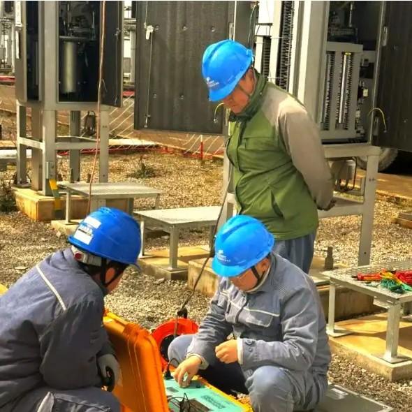
3.1 Timely Fault Detection and Response
Operators must conduct routine equipment checks, record operational data, and identify early fault signs. After maintenance, proper acceptance testing is critical to ensure safety.
In case of faults, operators should:
Isolate faulty equipment
Switch to backup systems
Apply effective solutions to maintain system stability
Mastering switching operations (isolator operations) significantly reduces fault risks. This requires high technical proficiency and continuous training.
3.2 Enforce Safety Regulations and Accountability
Enhance safety awareness through:
Bulletin boards
Safety slogans
Accident videos
Safety bulletins
Safety meetings
Case studies
Establish a safety responsibility system with clear roles, performance metrics, and reward/punishment mechanisms. Make safety responsibilities quantifiable and traceable to motivate operators and strengthen accountability.
3.3 Improve Technical Management
To ensure grid safety, operators must continuously improve technical skills and equipment management.
Conduct training programs, technical lectures, and regulation reviews.
Ensure staff understand:
Equipment layout
System connections
Operating procedures
Basic maintenance
Conduct accident anticipation exercises and anti-accident drills to improve emergency response.
Ensure operators fully understand:
Operation purpose
Pre- and post-operation system states
Load changes
Critical precautions
4. Conclusion
In modern society, people heavily rely on electricity for production and daily life, demanding higher reliability from power systems. Therefore, enhancing attention to substation operation, mastering tripping fault mechanisms, and responding promptly are essential tasks for the power industry to minimize system disruptions.