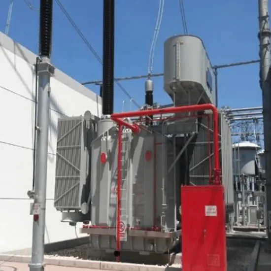
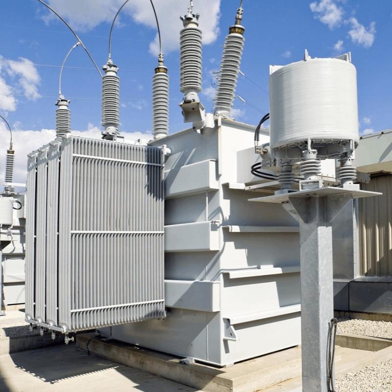
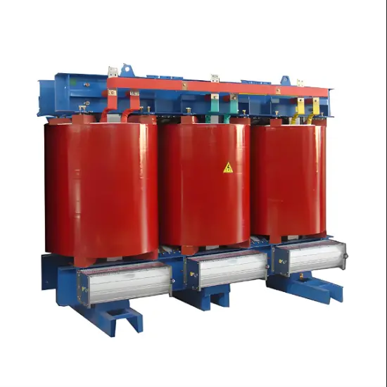
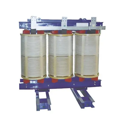
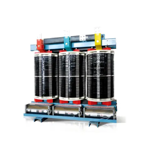
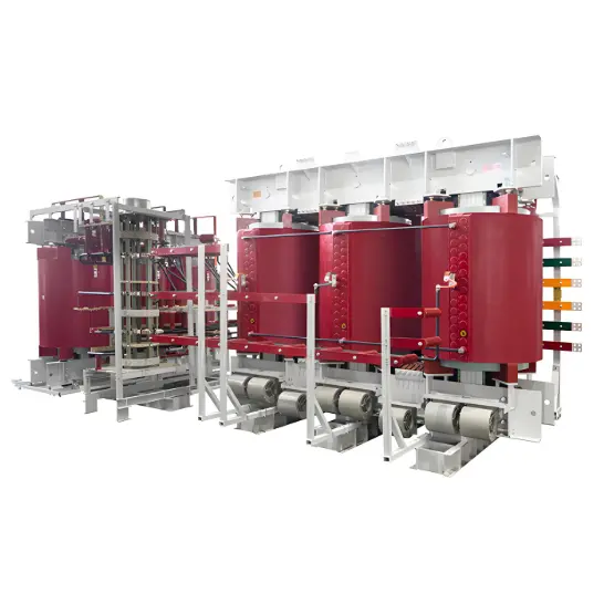
Transformer Definition
A transformer is defined as an electrical device that transfers electrical energy between two or more circuits through electromagnetic induction.
Theory of Transformer on No-Load
Having No Winding Resistance and No Leakage Reactance
Consider a transformer with only core losses, meaning it has no copper loss or leakage reactance of transformer. When an alternating current source is applied to the primary, it supplies current to magnetize the core of transformer.
But this current is not the actual magnetizing current; it is a little bit greater than actual magnetizing current. Total current supplied from the source has two components, one is the magnetizing current which is merely utilized for magnetizing the core, and another component of the source current is consumed for compensating the core losses in transformers.
Due to the core loss component, the no-load source current doesn’t lag the supply voltage by exactly 90° but by an angle θ, which is less than 90°. The total current Io has a component Iw in phase with the supply voltage V1, representing the core loss component.
This component is taken in phase with the source voltage because it is associated with active or working losses in transformers. Another component of the source current is denoted as Iμ.
This component produces the alternating magnetic flux in the core, so it is watt-less; means it is a reactive part of the transformer source current. Hence Iμ will be in quadrature with V1 and in phase with alternating flux Φ. Hence, the total primary current in a transformer on the no-load condition can be represented as:

Now you have seen how simple it is to explain the theory of transformer in no-load.

Theory of Transformer on Load
Having No Winding Resistance and Leakage Reactance

Now we will examine the behavior of the above-said transformer on load, which means the load is connected to the secondary terminals. Consider, a transformer having core loss but no copper loss and leakage reactance. Whenever a load is connected to the secondary winding, the load current will start to flow through the load as well as the secondary winding.
This load current solely depends upon the characteristics of the load and also upon the secondary voltage of the transformer. This current is called secondary current or load current, here it is denoted as I2. As I2 is flowing through the secondary, a self MMF in secondary winding will be produced. Here it is N2I2, where, N2 is the number of turns of the secondary winding of the transformer.

This MMF or magnetomotive force in the secondary winding produces flux φ2. This φ2 will oppose the main magnetizing flux and momentarily weakens the main flux and tries to reduce primary self-induced emf E1. If E1 falls below the primary source voltage V1, there will be an extra current flowing from source to primary winding.
This extra primary current I2′ produces extra flux φ′ in the core which will neutralize the secondary counter flux φ2. Hence the main magnetizing flux of core, Φ remains unchanged irrespective of load. So total current, this transformer draws from the source can be divided into two components.
The first one is utilized for magnetizing the core and compensating the core loss, i.e., Io. It is the no-load component of the primary current. The second one is utilized for compensating the counter flux of the secondary winding.
It is known as the load component of the primary current. Hence total no-load primary current I1 of an electrical power transformer having no winding resistance and leakage reactance can be represented as follows
Where θ2 is the angle between the Secondary Voltage and Secondary Current of the transformer.Now we will proceed one further step toward a more practical aspect of a transformer.
Theory of Transformer On Load, with Resistive Winding, but No Leakage Reactance
Now, consider the winding resistance of the transformer but no leakage reactance. So far we have discussed the transformer which has ideal windings, means winding with no resistance and leakage reactance, but now we will consider one transformer which has internal resistance in the winding but no leakage reactance. As the windings are resistive, there would be a voltage drop in the windings.

We have proved earlier that, total primary current from the source on load is I1. The voltage drop in the primary winding with resistance, R1 is R1I1. Obviously, induced emf across primary winding E1, is not exactly equal to source voltage V1. E1 is less than V1 by voltage drop I1R1.

Again in the case of secondary, the voltage induced across the secondary winding, E2 does not totally appear across the load since it also drops by an amount I2R2, where R2 is the secondary winding resistance and I2 is secondary current or load current.
Similarly, the voltage equation of the secondary side of the transformer will be:

Theory of Transformer On Load, with Resistance as well as Leakage Reactance
Now we will consider the condition when there is leakage reactance of the transformer as well as winding resistance of the transformer.

Let leakage reactances of primary and secondary windings of the transformer are X1 and X2 respectively. Hence total impedance of primary and secondary winding of transformer with resistance R1 and R2 respectively can be represented as,

We have already established the voltage equation of a transformer on load, with only resistances in the windings, where voltage drops in the windings occur only due to resistive voltage drop.
But when we consider leakage reactance of transformer windings, the voltage drop occurs in the winding not only due to resistance but also due to the impedance of transformer windings. Hence, the actual voltage equation of a transformer can easily be determined by replacing resistances R1 & R2 in the previously established voltage equations with Z1 and Z2.
Therefore, the voltage equations are,

Resistance drops are in the direction of the current vector. But a reactive drop will be perpendicular to the current vector as shown in the above vector diagram of the transformer.