Low Voltage Switchgear or LV Switchgear

03/25/2024

What Is Low Voltage Switchgear

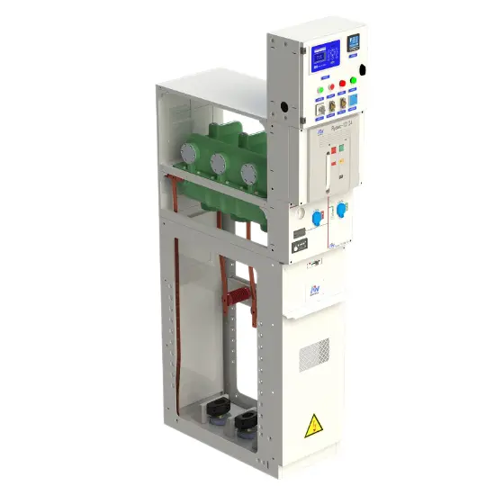
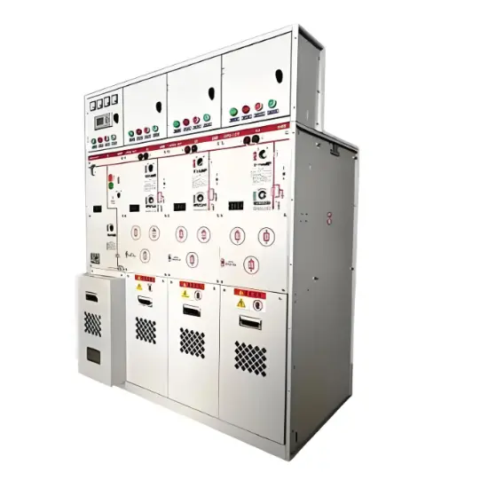
Generally electrical switchgear rated upto 1KV is termed as low voltage switchgear. The term LV Switchgear includes low voltage circuit breakers, switches, off load electrical isolators, HRC fuses, earth leakage circuit breaker, miniature circuit breakers (MCB) and molded case circuit breakers (MCCB) etc i.e. all the accessories required to protect the LV system. The most common use of LV switchgear is in LV distribution board. This system has the following parts

Incomer

The incomer feeds incoming electrical power to the incomer bus. The switchgear used in the incomer should have a main switching device. The switchgear devices attached with incomer should be capable of withstanding abnormal current for a short specific duration in order to allow downstream devices to operate. But it should be cable of interrupting maximum value of the fault current generated in the system. It must have an interlocking arrangement with downstream devices. Generally air circuit breakers are preferably used as interrupting device. Low voltage air circuit breaker is preferable for this purpose because of the following features

lv distribution board

  1. Simplicity

  2. Efficient performance

  3. High normal current rating up to 600 A

  4. High fault withstanding capacity upto 63 kA

Although air circuit breakers have long tripping time, big size, high cost but still they are most suitable for low voltage switchgear for the above-mentioned features.

Sub – Incomer

Next downstream part of the LV Distribution board is sub – incomer. These sub-incomers draw power from main incomer bus and feed this power to feeder bus. The devices installed as parts of a sub – incomer should have the following features

  1. Ability to achieve economy without sacrificing protection and safety

  2. Need for relatively less number of interlocking since it cover limited are of network.

ACBs (Air Circuit Breakers) and switch fuse units are generally used as sub – incomers along with molted case circuit breakers (MCCB).

Feeders

Different feeders are connected to the feeder bus to feeds different loads like, motor loads, lighting loads, industrial machinery loads, air conditioner loads, transformer cooling system loads etc. All feeders are primarily protected by switch fuse unit and in addition to that, depending upon the types of load connected to the feeders, the different switchgear devices are chosen for different feeders. Let us discuss in details

  • Motor Feeder

  • Motor feeder should be protected against over load, short circuit, over current up to locked rotor condition and single phasing.

  • Industrial Machinery Load Feeder

  • Feeder connected industrial machinery load like oven, electroplating bath etc are commonly protected by MCCBl and switch fuse disconnector units

  • Lighting Load Feeder

  • This is protected similar to industrial machinery load but additional earth leakage current protection is provided in this case to reduce any damage to life and property that could be caused by harmful leakages of current and fire.

In LV switchgear system, electrical appliances are protected against short circuit and overload conditions by electrical fuses or electrical circuit breaker. However, the human operator is not adequately protected against the faults occurs inside the appliances. The problem can be overcome by using an earth leakage circuit breaker. This operates on low leakage current. The earth leakage circuit breaker can detect leakage current as low as 100 mA and is capable of disconnecting the appliance in less than 100 msec.
low voltage switchgear or lv distribution board
A typical diagram of low voltage switchgear is shown above. Here the main incomer comes from LV side of an electrical transformer. This incomer through an electrical isolator as well as an MCCB (not shown in the figure) feeds the incomer bus. Two sub-incomers are connected to the incomer bus and these sub-incomers are protected by means of either switch fuse unit or air circuit breaker. These switches are so interlocked along with bus section switch or bus coupler that only one incomer switch can be put on if bus section switch is in on position and both sub incomer switches can be put on only if bus section switch is at off position. This arrangement is fruitful for preventing any mismatch of phase sequence between the sub – incomers. The different load feeders are connected to any of both sections of the feeder bus. Here motor feeder is protected by thermal overload device along with conventional switch fuse unit. Heater feeder is protected only by conventional switch fuse unit. The domestic lighting and AC loads are separately protected by a miniature circuit breaker along with common conventional switch fuse unit. This is most basic and simple scheme for low voltage switchgear or LV distribution board.

Statement: Respect the original, good articles worth sharing, if there is infringement please contact delete.

Wenzhou Rockwell Transformer Co., Ltd. It is a high - tech enterprise integrating R & D, production, sales, and service. It focuses on the manufacturing of power transformers and supporting equipment, and is committed to providing efficient, reliable, and energy - saving power transmission and distribution solutions for global customers. We can offer: •Distribution transformers and substations •Outdoor switchgears and breakers(recloser) •Switchgears and it’s components (GIS, RMU, VCB, SF6 CB) Market and Service: We always take customers as the orientation and provide customized services according to their requirements. Our products are exported to the Middle East, Africa, Northern Europe, South America, and many other countries and regions. Drive the future of electricity with technological innovation and become a leading global supplier of intelligent power equipment.

Ensuring Reliability: A Deep Dive into Transformer Maintenance
IntroductionElectric transformers are the backbone of modern power distribution systems, silently enabling the reliable delivery of electricity to homes, businesses, and industries. As these critical assets age and the demand for uninterrupted power grows, the importance of diligent transformer maintenance has never been greater. This essay explores the essential role of transformer maintenance, highlighting the value of proactive care, the impact of advanced diagnostic technologies, and the tra
Vziman
09/03/2025
How does a transformer work?
Transformer Operation PrincipleA transformer is an electrical device that operates on the principle of electromagnetic induction to transfer electrical energy from one circuit to another. It enables the adjustment of voltage levels within an alternating current (AC) system, either stepping up (increasing) or stepping down (decreasing) voltage while maintaining the same frequency.Working Principle:Basic ComponentsA transformer consists of two coils, known as windings—the "primary winding" connect
Rockwell
09/03/2025
What is the difference between a dielectric and an insulator?
Dielectrics and insulators are distinguished primarily by their applications. One of the main differences is that a dielectric can store electrical energy by becoming polarized in an electric field, whereas an insulator resists the flow of electrons to prevent current conduction. Other key differences between them are outlined in the comparison chart below.Definition of DielectricA dielectric material is a type of insulator that contains few or no free electrons. When subjected to an electric fi
08/30/2025
What losses occur during operation of the transformer? How to reduce losses?
Transformers experience various types of losses during operation, primarily categorized into two main types: copper losses and iron losses.Copper LossesCopper losses, also known as I²R losses, are caused by the electrical resistance of the transformer windings—typically made of copper. As current flows through the windings, energy is dissipated in the form of heat. These losses are proportional to the square of the load current (I²R), meaning they increase significantly with high
Rockwell
08/29/2025
Inquiry
Download
IEE-Business is dedicated to serving the personnel in the global power industry.
Join IEE-Business, not only can you discover power equipment and power knowledge, but also canhnd like - minded friends!