• Product
  • Suppliers
  • Manufacturers
  • Solutions
  • Free tools
  • Knowledges
  • Experts
  • Communities
Search


Fully air insulated switchgear of 12kV/24kV

  • Fully air insulated switchgear of 12kV/24kV

Key attributes

Brand ROCKWILL
Model NO. Fully air insulated switchgear of 12kV/24kV
Rated voltage 24kV
Rated normal current 630A
Rated frequency 50/60Hz
Rated short circuit breaking current 16kA
Series Eok

Product descriptions from the supplier

Description

Product overview

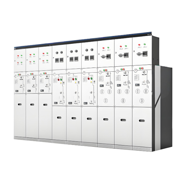
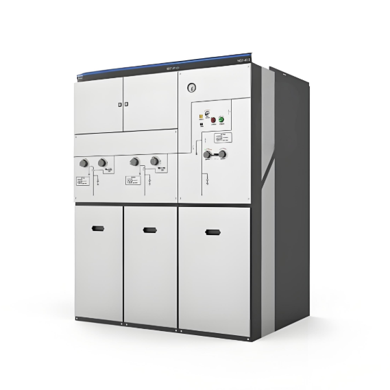
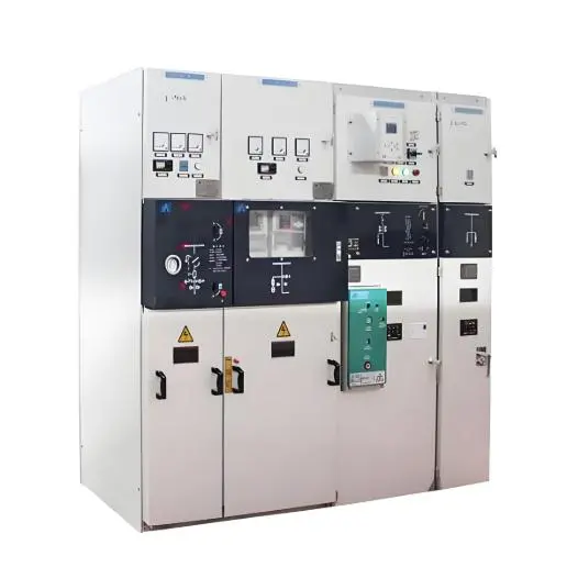
As the power industry evolves, the miniaturization of electrical equipment represents a key future trend and an urgent need for current power consumers. Miniaturized electrical equipment not only saves land and civil engineering costs but also reduces the use of greenhouse gases like sulfur hexafluoride (SF6), thereby meeting ecological and environmental protection requirements. Leveraging years of extensive experience in high-voltage electrical design and incorporating globally advanced technical design philosophies, our company has developed the latest The EoK-12/24 Fully air insulated switchgear This product is tailored for power utilities and enterprises pursuing high power supply reliability, advancing distribution automation upgrades, and operating in harsh environments. It serves not just as a simple line switch but as a critical component in building smart, resilient distribution grids.

Rysec of 12kV/24kV

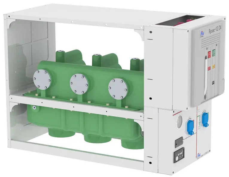
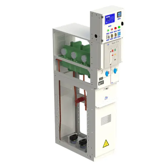
Product Structure Analysis
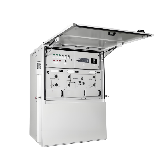
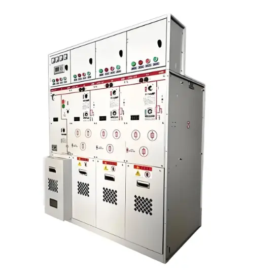
The product structure of ROCKWELL RySec Compact physically embodies its integrated multi-function concept. Its design is sophisticated and clearly layered, primarily consisting of three core components: the upper circuit breaker module, the lower isolation/earthing switch module, and the integrated operating and interlocking mechanism.

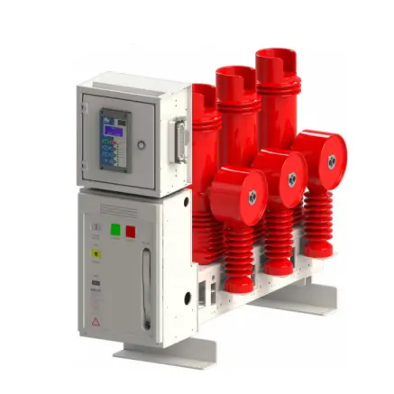
Upper Structure: Circuit Breaker Module

  1. Core Function: Undertakes the tasks of closing the circuit, carrying the load current, and interrupting fault currents.

  2. Casing Material: Fabricated using epoxy resin casting, which provides outstanding electrical insulation strength and mechanical strength.

  3. Arc Interruption Unit: Encapsulated within the casing are three vacuum interrupter chambers, the core interrupting components of the circuit breaker. These chambers efficiently and cleanly extinguish the arc at current zero-crossing points.

  4. Insulating Medium: The chamber is filled with Pure air/N2 gas as the insulating medium, ensuring high insulation performance within a compact design.

Lower Structure: Isolation and Earthing Switch Module

  1. Core Function: Provides physical isolation of the circuit (disconnector) and safe earthing of cables (earthing switch).

  2. Structural Material: Crafted from epoxy resin casting, delivering exceptional electrical insulation strength and mechanical robustness.

  3. Integrated Component: The lower housing incorporates a capacitive bushing, enabling connection to voltage indication equipment without the need for an additional, separate capacitive voltage divider within the switchgear.

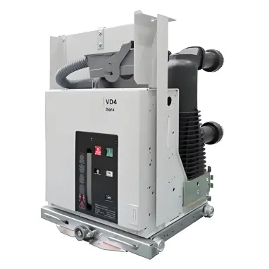
Operating and Interlocking Mechanism

   The RySec is equipped with two independent yet mechanically interlocked operating mechanisms, ensuring logical and safe operation sequences.

  • Circuit Breaker Operating Mechanism (EL Series)

1) Type: Spring-operated, trip-free mechanism.

2) Features:

a) Enables local (manual) or remote (electric) control via closing/opening coils and a motor.

b) Includes mechanical anti-pumping function to prevent repeated closing/latching under fault conditions.

c) Springs are charged during the closing operation, storing energy for rapid contact separation during tripping.

d) The mechanism is mechanically latched in the closed position and released by a separate trip signal, ensuring instantaneous opening independent of operator intervention.

  • Disconnector/Earthing Switch Operating Mechanism (1S Series)

1) Type: Double-spring operating mechanism.

2) Features:

a) Provides two independent operating interfaces for disconnector and earthed switch operations, respectively.

b) The operating force

  • Core Safety Structure: Mechanical Interlocking System

The most critical safety feature of the product structure is its built-in, non-bypassable mechanical interlocking system

1) Circuit Breaker-Disconnector Interlock

Prevents operation of the disconnector when the circuit breaker is in the closed position, avoiding load-breaking or making operations on the disconnector

2) Disconnector-Earthing Switch Interlock

Implemented via independent operating lever seats, ensuring:

a) The earthing switch can only be closed after the disconnector is fully open.

b) The disconnector can only be closed after the earthing switch is open

3) Cabinet Door Interlock

Mechanically linked to the switchgear door, ensuring:

a) The cable compartment door can be opened only when the disconnector is open and the earthing switch is closed (safely grounding the cable side).

b) When the door is open, the earthing switch is mechanically blocked from opening

Technical Parameters

Parameter Name

Value

Rated voltage

12KV

24KV

Insulation voltage

12KV

24KV

Power frequency withstand voltage (50/60 Hz, 1 min)

28KV

50KV

Lightning impulse withstand voltage (BIL 1.2/50 us)

75KV

125KV

Rated frequency

50/60Hz

50/60Hz

Rated current

630A

630A

Short-time withstand current (3s)

12.5/16/21KA

12.5/16/21KA

Performance of breaking part (lEC 62271-100)

Breaking capacity

-

Short-circuit current

12.5/16/21KA

No-load transformers

6.3A

No-load lines.

10A

No-load cables

16A

Capacitive currents

400A

Making capacity

32.5/41.5/45.5kAp

Operating sequence

O-0.3s-CO-15s-CO

Opening time

40~55ms

Arcing time

10~15ms

Total break-time

50~70ms

Closing time

40~55ms

Electrical life

E2

Mechanical life

M2. 10000 mechanical operations

Capacitive current breaking class

C2

Line disconnector performance (IEC 62271-102)

Electrical life

E0

Mechanical life

M0- 1.000 mechanical operations

Earthing switch performance (IEC 62271-102)

Electrical life

E2

Mechanical life

M0- 1.000 mechanical operations

Earthing switch making capacity

32.5/41.5/54.5kAp

Other characteristics

Center-distance between phases

230mm

Operating temperature

-15℃&~+40℃

Maximum installation altitude

3000masl

External Dimensions

Length

Width

Height

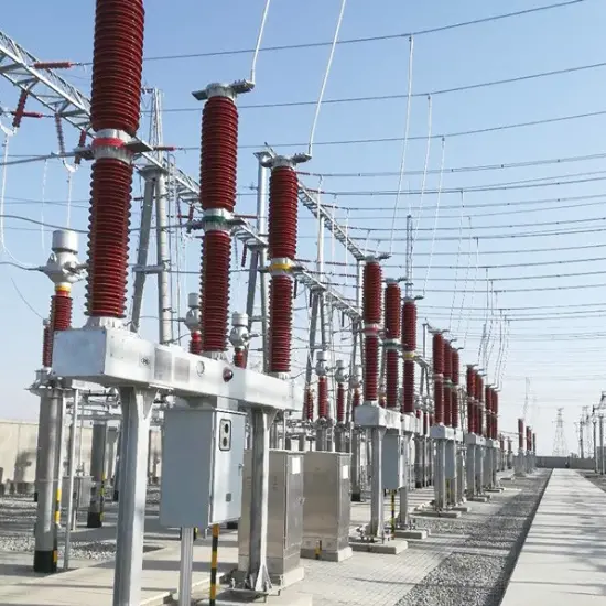
Application Scenarios

The RySec Compact is an ideal choice for secondary distribution applications, particularly suited for:

  1. Medium-sized distribution substations.

  2. Protection of overhead lines or cables.

  3. Switching of capacitor banks.

  4. Motor protection.


Documentation Resource Library
Restricted
Fully air insulated switchgear Catalogue
Catalogue
English
Consulting
Consulting
FAQ
Q: What are the core electrical and mechanical performance indicators of this equipment? Which of these indicators directly affect the performance of the equipment?
A:

Core electrical indicators: rated voltage of 12KV/24KV, rated current of 630A, short-time withstand current of 12.5/16/21KA, short-circuit current breaking capacity of 12.5/16/21KA, capacitor current breaking capacity of 400A; core mechanical indicators: circuit breaker mechanical life of 10000 times, opening/closing time of 40-55ms, total breaking time of 50-70ms. Impact effect:

  1. Rated voltage/current determines the level of medium voltage distribution system adapted to the equipment;
  2. The short-circuit withstand/break capacity is directly related to the arc extinguishing efficiency and safety protection capability of the equipment in the event of a fault;
  3. The mechanical lifespan and operating time affect the long-term stable operation duration and fault response speed of the equipment, ensuring the continuity of power supply.
Q: What are the main scenarios that this device is suitable for? What are the restrictions that must be paid attention to in terms of installation environment?
A:

The main applicable scenarios include medium-sized distribution stations, overhead line/cable protection, capacitor bank switching, and motor protection. Key limitations of installation environment:

  1. Temperature: The normal operating temperature range is -15 ℃ to+40 ℃. If you need to serve in an environment of -25 ℃ or store in an environment of -40 ℃, you need to contact the manufacturer in advance for customization;
  2. Altitude: The maximum installation altitude for conventional equipment is 1000m. For high-altitude areas exceeding this altitude, the manufacturer should be informed at the time of ordering and insulation reinforcement measures should be taken;
  3. Humidity: Suitable for high humidity environments with a daily average humidity of 100%, without the need for additional protection.
Q: What are the core competitive advantages of Eok-12/24 fully air insulated switchgear compared to traditional medium voltage switchgear?
A:


Answer: The core competitive advantages are concentrated in the four dimensions of "integration, safety, environmental protection, and efficiency":

  1. Compact integration, three in one design+environmentally friendly insulation medium, with a width of only 420mm, significantly saving space and infrastructure/material costs;
  2. Safety redundancy, built-in unavoidable mechanical interlocking system, eliminating misoperation from the root, circuit breaker with a mechanical lifespan of 10000 times and a sealing guarantee of more than 30 years for the shell, and reliability verification through full type testing;
  3. Green and environmentally friendly, using pure air/N ₂ to replace SF ₆ greenhouse gases, achieving zero carbon emissions and zero waste, in line with global environmental trends;
  4. The low TCO advantage reduces on-site assembly processes, supports plug and play accessories and quick customization, and lowers installation, maintenance, and long-term usage costs.
Know your supplier
Online store
On-time delivery rate
Response time
100.0%
≤4h
Company overview
Workplace: 108000m²m² Total staff: 700+ Highest Annual Export(usD): 150000000
Workplace: 108000m²m²
Total staff: 700+
Highest Annual Export(usD): 150000000
Services
Business Type: Design/Manufacture/Sales
Main Categories: High Voltage Electrical Apparatus/Electric transformer
Whole life care manager
Whole-life care management services for equipment procurement, use, maintenance, and after-sales, ensuring safe operation of electrical equipment, continuous control, and worry-free electricity consumption.
The equipment supplier has passed platform qualification certification and technical evaluation, ensuring compliance, professionalism, and reliability from the source.

Related Products

Related Knowledges

  • Impact of DC Bias in Transformers at Renewable Energy Stations Near UHVDC Grounding Electrodes
    Impact of DC Bias in Transformers at Renewable Energy Stations Near UHVDC Grounding ElectrodesWhen the grounding electrode of an Ultra-High-Voltage Direct Current (UHVDC) transmission system is located close to a renewable energy power station, the return current flowing through the earth can cause a rise in ground potential around the electrode area. This ground potential rise leads to a shift in the neutral-point potential of nearby power transformers, inducing DC bias (or DC offset) in their
    01/15/2026
  • HECI GCB for Generators – Fast SF6 Circuit Breaker
    1.Definition and Function1.1 Role of the Generator Circuit BreakerThe Generator Circuit Breaker (GCB) is a controllable disconnect point located between the generator and the step-up transformer, serving as an interface between the generator and the power grid. Its primary functions include isolating generator-side faults and enabling operational control during generator synchronization and grid connection. The operating principle of a GCB is not significantly different from that of a standard c
    01/06/2026
  • Distribution Equipment Transformer Testing, Inspection, and Maintenance
    1.Transformer Maintenance and Inspection Open the low-voltage (LV) circuit breaker of the transformer under maintenance, remove the control power fuse, and hang a “Do Not Close” warning sign on the switch handle. Open the high-voltage (HV) circuit breaker of the transformer under maintenance, close the grounding switch, fully discharge the transformer, lock the HV switchgear, and hang a “Do Not Close” warning sign on the switch handle. For dry-type transformer maintenance: first clean the porcel
    12/25/2025
  • How to Test Insulation Resistance of Distribution Transformers
    In practical work, insulation resistance of distribution transformers is generally measured twice: the insulation resistance between thehigh-voltage (HV) windingand thelow-voltage (LV) winding plus the transformer tank, and the insulation resistance between theLV windingand theHV winding plus the transformer tank.If both measurements yield acceptable values, it indicates that the insulation among the HV winding, LV winding, and transformer tank is qualified. If either measurement fails, pairwise
    12/25/2025
  • Design Principles for Pole-Mounted Distribution Transformers
    Design Principles for Pole-Mounted Distribution Transformers(1) Location and Layout PrinciplesPole-mounted transformer platforms should be located near the load center or close to critical loads, following the principle of “small capacity, multiple locations” to facilitate equipment replacement and maintenance. For residential power supply, three-phase transformers may be installed nearby based on current demand and future growth projections.(2) Capacity Selection for Three-Phase Pole-Mounted Tr
    12/25/2025
  • Transformer Noise Control Solutions for Different Installations
    1.Noise Mitigation for Ground-Level Independent Transformer RoomsMitigation Strategy:First, conduct a power-off inspection and maintenance of the transformer, including replacing aged insulating oil, checking and tightening all fasteners, and cleaning dust from the unit.Second, reinforce the transformer foundation or install vibration isolation devices—such as rubber pads or spring isolators—selected based on the severity of vibration.Finally, strengthen sound insulation at weak points of the ro
    12/25/2025

Related Solutions

  • Intelligent Operation Solution for 12kV Vacuum Circuit Breakers: Integrating Real-time Monitoring & Lifetime Optimization
    Ⅰ. Equipment Operation & MaintenanceIntelligent Monitoring System Integration​Multi-parameter Real-time Monitoring: Embedded sensors (temperature, displacement, Hall effect current sensors) track contact temperature rise, mechanical characteristics (opening/closing speed, overtravel), coil current, and partial discharge signals. Data undergoes preprocessing via edge computing prior to cloud upload.​Lifetime Prediction Model: Dynamically evaluates remaining lifespan using electrical wear data
    06/10/2025
  • SF6 Circuit Breaker Solutions for Outdoor Installation (Anti-Pollution & Seismic Resistance)
    I.Core Challenges in Outdoor Installation​In high-voltage transmission and distribution systems, SF6 circuit breakers are exposed to complex outdoor environments for extended periods, facing the following critical issues:​Pollution & Insulation Degradation​Dust, salt fog, and industrial pollutants in outdoor environments easily adhere to equipment surfaces. In coastal or industrial areas, pollution levels may reach ​Class IV, resulting in insufficient creepage distance and triggering ​flasho
    05/12/2025
  • 12kV Indoor Vacuum Circuit Breaker Southeast Asia Solution: Anti-Corrosion Compact Design
    12kV Indoor Vacuum Circuit Breaker Southeast Asia Solution: Anti-Corrosion Compact DesignⅠ. Executive Summary​Southeast Asia faces rapidly growing electricity demand alongside environmental challenges including high temperatures, humidity, salt spray corrosion, and grid instability. This solution recommends ​Solid Insulated Pole-Mounted Vacuum Circuit Breakers (VCB)​​ featuring ​high reliability, ​compact design, and ​smart monitoring. Tailored for tropical climates and industrial scenarios, it
    06/10/2025
Haven't found the right supplier yet? Let matching verified suppliers find you. Get Quotation Now
Haven't found the right supplier yet? Let matching verified suppliers find you.
Get Quotation Now
Send inquiry
+86

IEE Business will not sell or share your personal information.

Download
Get the IEE Business Application
Use the IEE-Business app to find equipment, obtain solutions, connect with experts, and participate in industry collaboration anytime, anywhere—fully supporting the development of your power projects and business.