• Product
  • Suppliers
  • Manufacturers
  • Solutions
  • Free tools
  • Knowledges
  • Experts
  • Communities
Search


Transformer Core-Lifting Inspection: Procedures, Safety, and Environmental Requirements

Rockwell
Rockwell
Field: Manufacturing
China

1.Environmental Requirements for Transformer Core-Lifting Inspection

1.1 General Environmental Conditions

Core - lifting operations are preferably carried out indoors. For large transformers that have to be operated outdoors due to specific conditions, sufficient measures must be taken to prevent moisture and dust contamination.

Core - lifting should not be conducted during rainy or snowy weather or when the relative humidity exceeds 75%.

The ambient air temperature during core - lifting should not be lower than 0°C, and the core temperature should not be lower than the surrounding air temperature. If the core temperature is lower, the transformer should be heated until its core temperature is approximately 10°C higher than the ambient temperature before the core - lifting can be carried out.

1.2 Air Exposure Time Limit

The exposure time of the core to air should be minimized. From the start of oil draining to oil refilling, the core's contact time with air must not exceed the following limits:

  • 16 hours when the relative humidity does not exceed 65%.

  • 12 hours when the relative humidity does not exceed 75%.

2 Transformer Core - Lifting Method
2.1 Preparation and Safety Checks

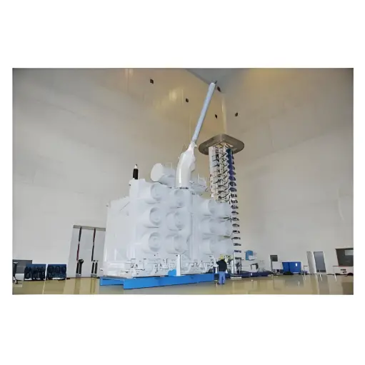
Before lifting the core, thoroughly check the strength of the steel wire ropes and the reliability of their connections. The angle between each lifting rope and the vertical line must not exceed 30°. If this requirement cannot be met, or if the lifting slings touch the core components, auxiliary lifting beams should be used to avoid excessive tension on the ropes or deformation of the lifting plates or rings. Lifting operations must be supervised by a designated person, and personnel should monitor all four corners of the tank to prevent collisions and damage to the core, windings, or insulation components.

  • Partial Oil Draining:Before lifting the core, drain some oil from the tank to prevent spillage when the top cover bolts are removed.

  • Inspection and Preparation:Remove the top cover to observe the internal condition. Record the position of the tap changer and mark it for reference. Dismantle the movable parts of the no - load tap changer.

  • Component Removal:Dismantle the bushings, oil conservator, protective pipes, fan motors, radiators, tap changer operating mechanisms, oil purifier, thermometer, and top cover bolts.

  • Disconnection of Core Components:Remove the transformer top cover, ensuring that all connections between the core and the top cover are detached before lifting the top cover.

  • Core Lifting:If the lifting equipment is mobile, the core can be lifted to the designated inspection location. If the lifting equipment is fixed, move the tank away after lifting the core and lower the core for inspection.

  • Removal of Insulating Wrapping:If present, remove the insulation wrapping on the core (mark it beforehand for reassembly).

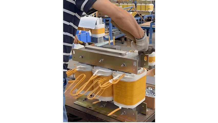
  • Cleaning and Inspection:Use clean cloths to wipe the windings, core supports, and insulation barriers, checking for metal debris such as iron filings adhering to the core.

3 Inspection Items During Transformer Core - Lifting
3.1 Core Inspection

  • Inspect the tightening bolts and nuts on the silicon steel sheets and the structural steel securing the core yoke. Ensure all nuts are fastened securely.

  • Check the effectiveness of the core's single - point grounding connection copper strip.

  • For large transformers, inspect the longitudinal cooling channels in the core columns and remove any blockages.

3.2 Winding Inspection

  • Inspect the axial compression of the windings.

  • Ensure the inter - layer spacers are secure, with no looseness, deformation, or displacement.

  • Verify that the high and low - voltage windings are symmetrical, free from adhesive contamination, and that the insulation layers are intact without discoloration, cracking, or breakdown defects.

3.3 Core Insulation Inspection

  • Check the physical integrity of core insulation, including paper insulation on winding surfaces and lead insulation wrapping.

  • Clean the core insulation surface of oil sludge and dirt, if present.

  • Inspect inter - phase and inter - coil insulation barriers.

  • For aged transformers, test for insulation aging. Signs include cracks under finger pressure, hardened and brittle texture, and darker color. Severe aging may cause insulation to shatter and become carbonized under pressure, indicating the need for replacement.

4. Lead and Support Structure Inspection

  • Ensure the insulation distance of leads meets requirements.

  • Check the tightness of clamping parts to maintain lead insulation distance.

  • Inspect the insulation on lead surfaces and ensure that soldering and connections are secure without any broken strands.

5. No - Load Tap Changer Inspection

  • Inspect the contact pressure between moving and stationary contacts, which should be 25–50 N.

  • Ensure good contact at all switching positions, particularly the position in use.

  • Check for overheating signs at contact points, and verify the tap changer's overall stability and the flexibility of the mechanical operating device.

6. Oil Tank Cleaning and Inspection

  • Ensure the oil tank bottom is clean and free from sludge or debris, with no internal corrosion.

  • After core inspection, flush the tank with qualified transformer oil, then open the tank drain to remove residual oil. Immediately reinstall the core and refill the tank with oil to the normal level.

Give a tip and encourage the author!
Recommended
What Are the Types of Reactors? Key Roles in Power Systems
Reactor (Inductor): Definition and TypesA reactor, also known as an inductor, generates a magnetic field within the surrounding space when current flows through a conductor. Therefore, any current-carrying conductor inherently possesses inductance. However, the inductance of a straight conductor is small and produces a weak magnetic field. Practical reactors are constructed by winding the conductor into a solenoid shape, known as an air-core reactor. To further increase inductance, a ferromagnet
James
10/23/2025
35kV Distribution Line Single-Phase Ground Fault Handling
Distribution Lines: A Key Component of Power SystemsDistribution lines are a major component of power systems. On the same voltage-level busbar, multiple distribution lines (for input or output) are connected, each with numerous branches arranged radially and linked to distribution transformers. After being stepped down to low voltage by these transformers, electricity is supplied to a wide range of end users. In such distribution networks, faults such as phase-to-phase short circuits, overcurre
Encyclopedia
10/23/2025
Why Does MVDC Grounding Cause System Faults?
Analysis and Handling of DC System Grounding Faults in SubstationsWhen a DC system grounding fault occurs, it can be classified as single-point grounding, multi-point grounding, loop grounding, or reduced insulation. Single-point grounding is further divided into positive-pole and negative-pole grounding. Positive-pole grounding may cause misoperation of protection and automatic devices, while negative-pole grounding may lead to failure to operate (e.g., relay protection or tripping devices). On
Felix Spark
10/23/2025
MVDC: Future of Efficient, Sustainable Power Grids
The Global Energy Landscape Is Undergoing a Fundamental Transformation toward a "fully electrified society," characterized by widespread carbon-neutral energy and the electrification of industry, transportation, and residential loads.In today’s context of high copper prices, critical mineral conflicts, and congested AC power grids, Medium-Voltage Direct Current (MVDC) systems can overcome many limitations of traditional AC networks. MVDC significantly enhances transmission capacity and efficienc
Edwiin
10/21/2025
Related Products
Send inquiry
Download
Get the IEE Business Application
Use the IEE-Business app to find equipment, obtain solutions, connect with experts, and participate in industry collaboration anytime, anywhere—fully supporting the development of your power projects and business.