1. Introduction
Building electrical engineering is an indispensable component of modern construction projects. The installation of electrical riser lines and distribution boxes is of paramount importance to the integrity and functionality of the entire electrical system. The quality of riser line installation directly impacts the usability, safety, and operational efficiency of the entire building. Therefore, rigorous quality control measures for the construction of electrical riser lines and distribution boxes are essential to prevent economic losses and ensure occupant safety.
In public buildings, electrical risers primarily serve as the main power supply conduits for lighting, power loads, and other equipment on each floor. Any quality issues within the riser can have a direct and cascading impact on the entire building's electrical infrastructure. Thus, strict control over construction quality is critical to guarantee the overall quality of the building's electrical engineering. This ensures that all parameters comply with national construction safety standards and safeguard the normal daily lives of occupants.
2. Overview of Building Electrical Riser Engineering
The standard power supply voltage for building electrical systems is 380/220V, utilizing flame-retardant power cables. High and low voltage distribution rooms are typically located on the first basement level, with power distributed to each floor via electrical risers. The lightning protection level is classified as Grade 1, and the grounding protection system employs the TN-S configuration.
The installation of riser lines significantly influences the functionality of the entire building. Consequently, any hidden defects or improper installations within the electrical riser can pose serious safety threats to the entire construction project, potentially leading to fire hazards, electrical failures, or compromised structural integrity.
3. Preparation Work for Installing Building Electrical Riser Lines
3.1 Pre-embedding of Openings in Electrical Risers
Electrical riser rooms generally require the installation of basic auxiliary facilities such as cable trays, distribution boxes, cable bridges, and associated cabling. Prior to pre-embedding, the positions of all electrical equipment and conduits within the riser must be accurately laid out according to the design drawings. If discrepancies are found between the marked dimensions on the drawings and the actual site conditions, timely adjustments must be made to ensure the correct installation of electrical conduits and equipment at a later stage, preventing costly rework.
3.2 Precautions During the Pre-embedding of Electrical Conduits
The pre-embedding of conduits must be meticulously planned based on the height, dimensions, and specific locations of the electrical distribution boxes. This ensures that conduits are neatly aligned and unobstructed, guaranteeing the correct routing and connection of cables. The proper and correct installation of distribution boxes significantly enhances the accuracy, reliability, and aesthetic quality of the riser line connections. Therefore, the overall installation should aim to create an electrical riser that optimally combines economy, aesthetics, and reliability.
4. Quality Control for the Installation of Electrical Riser Lines and Distribution Boxes
4.1 Quality Control for Busway Installation
Joint Positioning and Protection: Connection joints for the busway should not be located at floor slabs. The distance from the joint to the building floor should be a minimum of 650mm. To protect the busway during installation, its outer shell should be wrapped with plastic film to prevent physical damage or water ingress, thereby ensuring installation quality.
Insulation Testing: Before installation, the insulation resistance of the busway must be measured using a megohmmeter. Installation can only proceed if the resistance exceeds 20MΩ. For enclosed busways, a 2500V megohmmeter is required to measure the insulation resistance of each functional unit, which must also exceed 20MΩ. This test is critical and must be performed before and during installation.
Component Verification: Technicians must verify the specifications and models of all busway components against the system diagram to prevent blind installation, which can lead to rework, unnecessary losses, and compromised construction quality.
Floor Penetration Support: When the busway passes through a building floor slab, use 1–3 bolts (matching the busway size) to fix springs and specialized support attachments. Securely connect the support to the floor slab using nuts, flat washers, bolts, and spring washers to properly support the busway column. (Refer to Fig. 1: 1 - Channel steel, 2 - Bolt, 3 - Spring support, 4 - Specialized attachment).
4.2 Quality Control for the Installation of Cable Trays and Raceways
The technical parameters for cable trays and raceways must strictly adhere to the design drawings, with a reasonable allowance reserved to ensure the correct installation of cables at a later stage. The installation must ensure the rationality of the cable tray routing and the convenience of raceway installation. On-site construction personnel must thoroughly analyze the construction drawings, understand the specified installation methods, and be prepared to make adjustments based on actual site conditions to ensure a correct and compliant installation.
4.3 Laying of Power Cables
The cable installation method must be determined by combining the electrical construction drawings with the on-site conditions, ensuring the process is effective, rational, scientific, and convenient. The two primary cable installation methods are:
Rigid protective sleeves are typically installed at points where cables are susceptible to damage (e.g., where they pass through walls or floors) to protect power cables from abrasion or impact.
5. Quality Control for the Installation of Building Electrical Distribution Boxes
Selection and Cost Estimation: Before installation, the quality of the distribution boxes must be carefully selected. While ensuring quality, costs should be minimized. The estimation formula for distribution boxes can be used: A = ∑BK + C + D, where:
5.1 Installation of Building Electrical Distribution Boxes
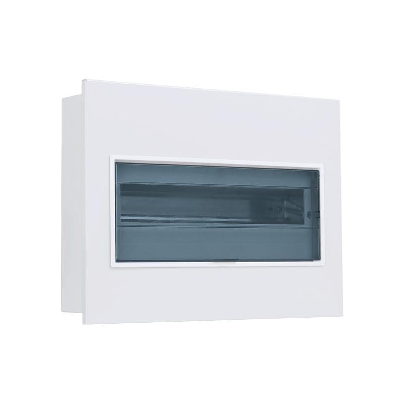
Positioning and Integrity: The installation position of electrical distribution boxes must be accurate, with all components complete and undamaged.
Conduit Entry: Openings in the box must match the conduit diameter. Conduits should be secured using lock nuts. The conduit entry into the box should typically be 3–5mm.
Secure Fixing: When fixing the distribution box to the building structure, the connections must be robust and secure.
Installation Methods: Common methods include laying along raceways or using exposed conduits.Regardless of the method, specialized cutting tools must be used to maintain the overall aesthetics of the installation.
Hole Drilling: If standard knockouts do not meet requirements, new holes must be re-drilled using a sheet metal drill; punching or burning holes is prohibited.
Labeling and Wiring: Inside the distribution box, all circuits and important information must be clearly and permanently labeled. Avoid drilling holes on the sides of the box to prevent incoming/outgoing wires from contacting grounding or neutral wires, which poses a significant safety hazard.
Accessibility: For wall-mounted distribution boxes, ensure the door can open to at least 180° for full access to internal components.
Internal Wiring: Keep internal wiring neat and orderly, without any twisting or crossing . When connecting wires with pressure plates, ensure they are tightened securely to prevent loosening.
5.2 Installation of Floor-Mounted Cabinets
Base Support: Use channel steel as a base support for floor-mounted electrical cabinets, strictly following the dimensions and positions indicated in the drawings.
Conduit Entry: Conduit openings entering the cabinet should extend 50–80mm above the base of the cabinet.
Secure Connection: Connect the cabinet to the base channel steel using galvanized bolts and lock washers to ensure a secure, corrosion-resistant, and vibration-resistant connection.
Base Height: The top of the base channel steel should be 10mm above the finished floor level to prevent water ingress and allow for leveling.
6. Waterproof and Fireproof Sealing of Openings in Risers
According to relevant fire protection standards, improperly sealed openings in risers can create a "chimney effect" during a fire, allowing flames and smoke to spread rapidly between floors. Therefore, all penetrations through floor slabs within the riser must be properly sealed, and this critical task requires meticulous attention from technical personnel.
Sealing Procedure: The standard method involves using expansion bolts to fix a fireproof barrier (such as a fire-rated board or a 2mm thick steel plate) to the underside of the floor slab. The opening is then sealed, and the space is filled with approved fireproof sealing material (e.g., firestop mortar, putty, or mineral wool). (Refer to Fig. 2).
Waterproofing: A 30–50mm high waterproof barrier (or "drip ring") should be constructed around he top of the sealed opening to prevent water from entering the fireproof material, which could compromise its fire-resistance rating.
Importance: Strengthening the waterproof and fireproof sealing of riser openings is essential for ensuring the overall construction quality and safety of the building. This task is of the utmost importance; if neglected, it could lead to catastrophic losses, affect the entire project, and pose severe threats to human life and property.


