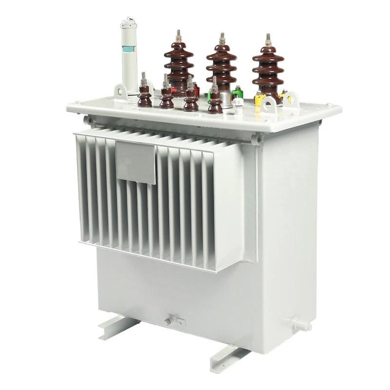
Measures to Prevent H59 Oil Immersed Power Distribution Transformer from Burning Out
In power systems, H59 Oil Immersed Power Distribution Transformer play an extremely critical role. Once burned out, they can cause widespread power outages, directly or indirectly affecting the production and daily lives of a large number of electricity users. Based on the analysis of multiple transformer burnout incidents, the author believes that a considerable number of such failures could have been avoided or eliminated at an early stage by implementing the following preventive measures.
1.Pre-Commissioning Inspection of H59 Oil Immersed Power Distribution Transformer
To ensure that the H59 Oil Immersed Power Distribution Transformer is ready for operation and to prevent burnout, on-site inspections must be conducted before commissioning. The main inspection items include:
Check whether the oil level gauge on the conservator tank is intact and whether the oil level is appropriate. If the oil level is too high, the oil may expand due to temperature rise after the transformer is energized under load and possibly overflow from the breather connection pipe at the top of the conservator. If the oil level is too low, it may drop below visible levels during light-load winter operation or short-term shutdowns, reducing the transformer’s insulation and cooling performance and affecting its operation.
Inspect whether covers, bushings, oil level gauges, drain valves, etc., are well sealed and free of oil leakage. Otherwise, more severe leakage may occur under thermal conditions once the transformer is loaded.
Check whether the explosion-proof diaphragm of the pressure relief device (explosion vent) is intact.
Inspect bushings for damage, cracks, or signs of discharge.
Verify whether the desiccant (silica gel) inside the breather (silica gel canister) has become ineffective.
Confirm that the transformer tank grounding is firm and reliable.
Check whether the primary and secondary bushings and their connections to conductors are secure and whether phase color markings are correct.
Verify that the nameplate data matches the required transformer specifications, including voltage ratings on all sides, winding connection group, rated capacity, and tap changer position.
Measure insulation resistance using a 1,000–2,500 MΩ megohmmeter to test the insulation resistance of both primary and secondary windings to ground and between windings. Record the ambient temperature during measurement. Although there is no rigid standard for acceptable insulation resistance values, the measured values should be compared with historical or factory data and should not fall below 70% of the original value.
Measure the DC resistance of the transformer windings together with bushings. For distribution transformers, the difference between phase DC resistances should be less than 4% of the average value, and the difference between line-to-line DC resistances should be less than 2% of the average value.
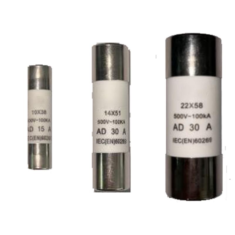
Check whether fuse selection is appropriate. The primary-side fuse should be rated at 1.5–2 times the transformer’s rated current, while the secondary-side fuse should typically match the secondary rated current.
If all the above inspections pass, the transformer should first be energized without load (“cold energization”). During this test, check for abnormal electromagnetic noise and measure whether the secondary voltages are balanced. Balanced voltages indicate normal turns ratio and absence of inter-turn short circuits, confirming the transformer is ready for normal loaded operation.

2. Operational Precautions for H59 Oil Immersed Power Distribution Transformer
During operation, regularly monitor whether the three-phase voltages are balanced. If significant imbalance is detected, take corrective actions immediately. Also, routinely inspect oil level and oil color, and check the tank for oil leaks. Address any defects promptly to prevent tap changers or windings from burning out due to moisture ingress.
Regularly clean dirt and contaminants from the transformer surface. Inspect bushings for flashover or discharge, verify good grounding, and check for broken, poorly soldered, or fractured grounding conductors. Periodically measure ground resistance—ensuring it does not exceed 4 Ω for transformers ≥100 kVA or 10 Ω for transformers <100 kVA—or implement anti-pollution measures such as installing pollution-resistant bushing caps.
When connecting or disconnecting transformer leads, strictly follow inspection and installation procedures to avoid internal conductor breakage. Select appropriate connection methods for secondary conductors.
When installing surge arresters on both primary and secondary sides of the H59 Oil Immersed Power Distribution Transformer, connect the arrester grounding lead, transformer tank, and secondary neutral point to a common grounding point. Conduct regular preventive tests and promptly replace any defective arresters to reduce the risk of overvoltage damage caused by lightning or resonance.
When switching the off-load tap changer, always measure DC resistance twice after each tap change, record the values, and compare the three-phase DC resistances for balance. Only put the transformer back into service after confirming normal tap operation. When measuring across all tap positions, keep detailed records and ensure the DC resistance of the operating tap is measured last.
Implement effective load monitoring and management for each service area. Promptly replace transformers in areas experiencing overload to prevent burnout due to prolonged overloading.