• Product
  • Suppliers
  • Manufacturers
  • Solutions
  • Free tools
  • Knowledges
  • Experts
  • Communities
Search


CLMD Series Capacitors unit

  • CLMD Series Capacitors unit

Key attributes

Brand Wone Store
Model NO. CLMD Series Capacitors unit
Rated voltage 380V
Rated capacity 30KVA
Series CLMD Series

Product descriptions from the supplier

Description

Overview

Design

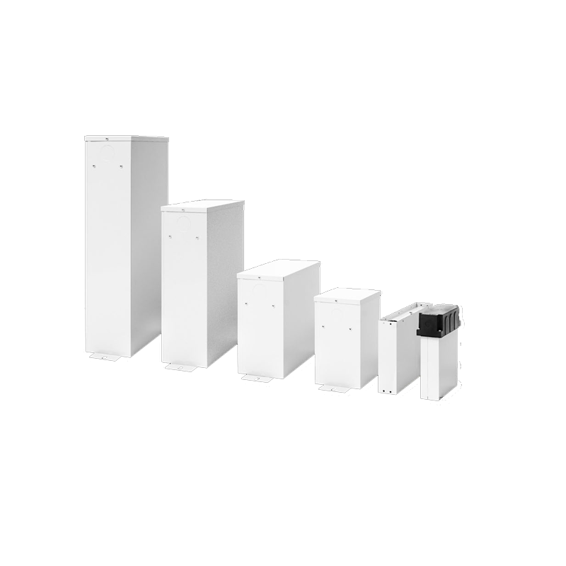
The building block of each CLMD capacitor unit is a capacitor winding. These windings undergo vacuum treatment to ensure consistent electrical characteristics. Each winding is then placed in a plastic case and

encapsulated in thermo-setting resin in order to obtain a perfectly sealed element. Elements are combined together to form the capacitor unit.

Electrical characteristics

Dielectric losses are less than 0.2 Watt per kvar. Total losses, including discharge resistors, are less than 0.5 Watt per kvar.

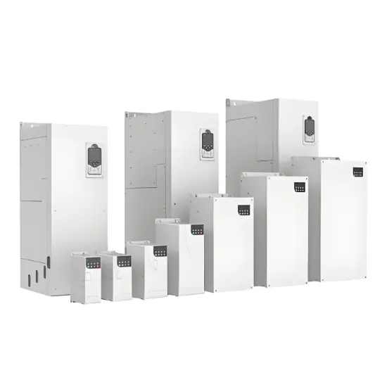
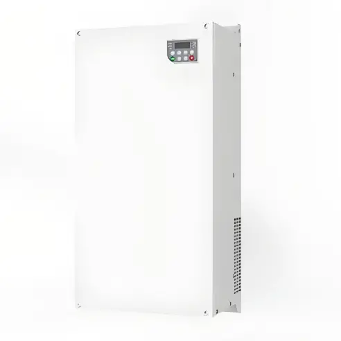
Available for single and three-phase systems The elements are placed inside a box made of sheet steel and connected in such a way as to supply the single or three-phase power at the required voltage and frequency.

Safe performance throughout the capacitor’s life
● The dry type dielectric makes the CLMD capacitors leakage free, minimizing the impact on the environment.
● The sheet steel box is filled with vermiculite which is an inorganic, inert and fireproof material that can absorb the energy produced or extinguish any flames in case of a possible defect at the end of an element’s life.
● In the event of a fault developing in the dielectric of the capacitor, the metallized electrode adjacent to the fault is immediately vaporized, thus isolating the fault. The capacitor then continues normal operation. This is commonly called the ‘self-healing’ principle.
● The capacitor windings are provided with a sequential disconnecter ensuring that each element can be reliably and selectively disconnected from the circuit at the end of its life.
● CLMD capacitors are provided with thermal equalizers to ensure effective heat dissipation. Discharge resistors are also included.
● The use of robust terminals minimizes the risk of damage during installation and reduces maintenance requirements.
● The capacitors comply with the requirements of IEC 60831-1 & 2.

High performance in-house metallized film
Completely integrated manufacturing process has resulted in the development of a special high-performance in-house metallized film from which all CLMD capacitors bene-fit. This film gives high breakdown strength, excellent peak cur-rent handling capability, and high capacitance stability and has an optimal self-healing design and a long life.

Technology parameters

Documentation Resource Library
Restricted
capacitors CLMD Data sheet
Operation manual
English
Consulting
Consulting
Know your supplier
Online store
On-time delivery rate
Response time
100.0%
≤4h
Company overview
Workplace: 1000m² Total staff: Highest Annual Export(usD): 300000000
Workplace: 1000m²
Total staff:
Highest Annual Export(usD): 300000000
Services
Business Type: Sales
Main Categories: Wire cable/High Voltage Electrical Apparatus/Low Voltage Electrical Apparatus/Instrument meters/New energy/Tester/Integrated Electrical Equipment/Production equipment/Generator/Electrical fittings/Instrument Transformer/Equipment Parts
Whole life care manager
Whole-life care management services for equipment procurement, use, maintenance, and after-sales, ensuring safe operation of electrical equipment, continuous control, and worry-free electricity consumption.
The equipment supplier has passed platform qualification certification and technical evaluation, ensuring compliance, professionalism, and reliability from the source.

Related Products

Related Knowledges

  • Faults and Handling of Single-phase Grounding in 10kV Distribution Lines
    Characteristics and Detection Devices for Single-Phase Ground Faults1. Characteristics of Single-Phase Ground FaultsCentral Alarm Signals:The warning bell rings, and the indicator lamp labeled “Ground Fault on [X] kV Bus Section [Y]” illuminates. In systems with a Petersen coil (arc suppression coil) grounding the neutral point, the “Petersen Coil Operated” indicator also lights up.Insulation Monitoring Voltmeter Indications:The voltage of the faulted phase decreases (in
    01/30/2026
  • Distribution Equipment Transformer Testing, Inspection, and Maintenance
    1.Transformer Maintenance and Inspection Open the low-voltage (LV) circuit breaker of the transformer under maintenance, remove the control power fuse, and hang a “Do Not Close” warning sign on the switch handle. Open the high-voltage (HV) circuit breaker of the transformer under maintenance, close the grounding switch, fully discharge the transformer, lock the HV switchgear, and hang a “Do Not Close” warning sign on the switch handle. For dry-type transformer maintenance: first clean the porcel
    12/25/2025
  • How to Test Insulation Resistance of Distribution Transformers
    In practical work, insulation resistance of distribution transformers is generally measured twice: the insulation resistance between thehigh-voltage (HV) windingand thelow-voltage (LV) winding plus the transformer tank, and the insulation resistance between theLV windingand theHV winding plus the transformer tank.If both measurements yield acceptable values, it indicates that the insulation among the HV winding, LV winding, and transformer tank is qualified. If either measurement fails, pairwise
    12/25/2025
  • Design Principles for Pole-Mounted Distribution Transformers
    Design Principles for Pole-Mounted Distribution Transformers(1) Location and Layout PrinciplesPole-mounted transformer platforms should be located near the load center or close to critical loads, following the principle of “small capacity, multiple locations” to facilitate equipment replacement and maintenance. For residential power supply, three-phase transformers may be installed nearby based on current demand and future growth projections.(2) Capacity Selection for Three-Phase Pole-Mounted Tr
    12/25/2025
  • Risk Identification and Control Measures for Distribution Transformer Replacement Work
    1.Electric Shock Risk Prevention and ControlAccording to typical design standards for distribution network upgrades, the distance between the transformer’s drop-out fuse and the high-voltage terminal is 1.5 meters. If a crane is used for replacement, it is often impossible to maintain the required minimum safety clearance of 2 meters between the crane boom, lifting gear, slings, wire ropes, and the 10 kV live parts, posing a severe risk of electric shock.Control Measures:Measure 1:De-energize th
    12/25/2025
  • Analysis of Common Faults and Causes in Routine Inspection of Distribution Transformers
    Common Faults and Causes in Routine Inspection of Distribution TransformersAs the terminal component of power transmission and distribution systems, distribution transformers play a critical role in supplying reliable electricity to end users. However, many users have limited knowledge of power equipment, and routine maintenance is often carried out without professional support. If any of the following conditions are observed during transformer operation, immediate action should be taken: Excess
    12/24/2025
Haven't found the right supplier yet? Let matching verified suppliers find you. Get Quotation Now
Haven't found the right supplier yet? Let matching verified suppliers find you.
Get Quotation Now
Send inquiry
+86
Click to upload file
Download
Get the IEE Business Application
Use the IEE-Business app to find equipment, obtain solutions, connect with experts, and participate in industry collaboration anytime, anywhere—fully supporting the development of your power projects and business.