| Brand | Vziman |
| Model NO. | 35kv Three-phase Epoxy Cast Dry Distribution Transformer |
| Rated capacity | 2000kVA |
| Voltage grade | 35KV |
| Series | Dry Distribution Transformer |
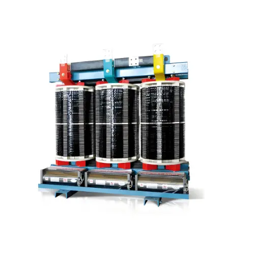
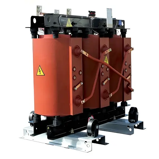
Product overview:
Lower loss, more energy saving, 30% energy saving than SCB11 transformer loss.
Actual measurement is better than GB and IEC standards, CB, CCC, KEMA SASO and other certification.
Better safety excellent fire performance, F1 class.
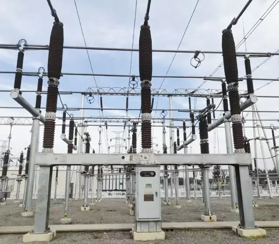
High lightning resistance level (175kV for 35kV products).
Equipped with perfect temperature protection control system, it can operate at 120% rated load under forced air cooling condition.
Global operation verified high reliability, has been exported to more than 50 countries and regions.
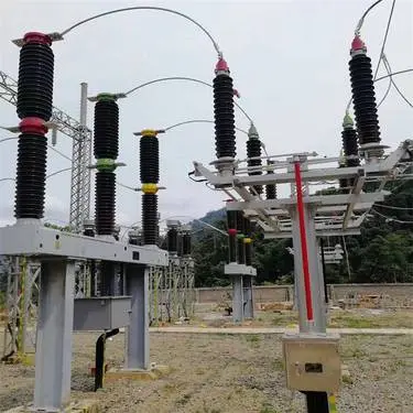
Mainly used in 35KV urban distribution network, industrial and mining enterprises and civil building power supply and distribution system.
Products are mainly exported to Southeast Asia, the Middle East, Africa, South America and other countries and regions.
Implementation standard: IEC 60076 series, GB1094 series, GB/T6451-2008.
The shell material is aluminum alloy, cold rolled steel plate, stainless steel, etc. (protection grade IP20, IP23, etc.))
Product advantages
Leading technology
High pressure copper tape winding technology, flame retardant formula vacuum pouring.
Low pressure copper foil winding technology, thermosetting epoxy prepreg cloth insulation.
High quality iron core 45° full oblique joint step laminated structure.
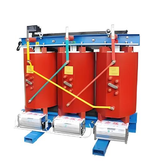
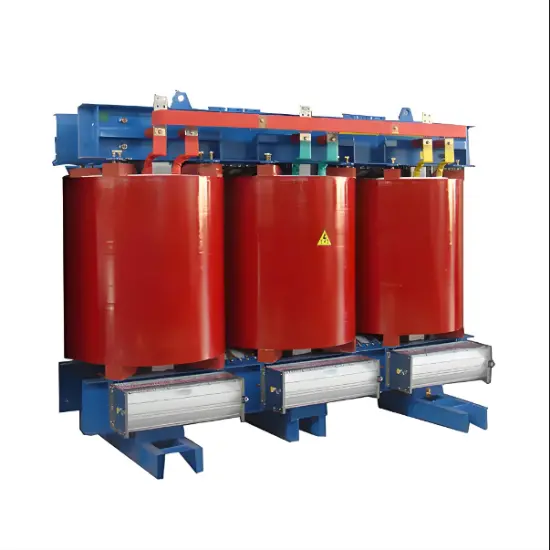
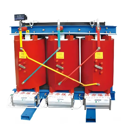
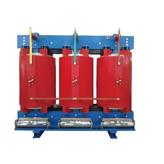
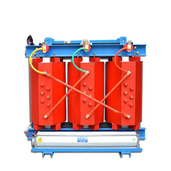
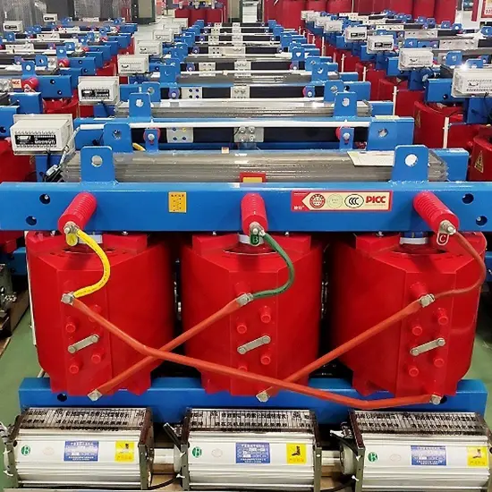
The iron core
The core is made of high quality cold rolled grain oriented silicon steel sheet insulated by mineral oxide.
Minimize loss level, no-load current and noise by controlling the cutting and stacking process of silicon steel sheet.
Apply class F or CLASS H core paint on the surface of assembled cores to prevent corrosion and rust.
Low voltage winding
The low voltage winding is made of high quality copper foil.
Insulated by thermosetting epoxy preimpregnated cloth.
Winding ends are insulated with thermosetting epoxy preimpregnated cloth.
Excellent insulation resistance.
Very good resistance to radial stress caused by short circuit.
The outgoing terminal of the low-voltage winding is tinned copper bar.
The whole winding is heated in the oven to 140°C and polymerized for 4 hours. It has excellent corrosion resistance of industrial gas.
High voltage winding
Made of insulated copper wire and using the patented technology of Hengfengyou Electric.
For small volume products, the high voltage winding uses a linear voltage gradient from top to bottom.
For products with large capacity, the high voltage winding is made by "tape winding" technology.
The application of these methods makes the electric field between adjacent conductors very low.
Transformer structure is reliable during normal operation and transportation.
High quality material
Baowu Steel Group production of silicon steel sheet.
China produces high quality anaerobic copper.
Huntsman Epoxy resin (including flame retardant filler).
Product parameters
Ordering instructions
Main parameters of transformer (voltage, capacity, loss and other main parameters.
Transformer operating environment (altitude, temperature, humidity, location, etc.
Other customization requirements (coupling groups, colors, oil pillows, etc.
The minimum order quantity is 1 sets, worldwide delivery within 7 days.
Normal delivery period of 30 days, worldwide fast delivery.
What is the epoxy casting process for the windings and core z of the transformer?
Manufacture of Windings and Iron Cores:
Windings Manufacture:
Use a wire winding machine to wind the copper wires into the required shapes and number of layers.
Ensure the uniformity and compactness of the windings.
Add insulating materials, such as insulating paper or insulating tape, between each layer of copper wires.
Iron Core Manufacture:
Use a silicon steel sheet laminating device to laminate the silicon steel sheets into an iron core.
Ensure the flatness and compactness of the iron core.
Conduct necessary pre-treatments on the iron core, such as deburring and cleaning.
Assembly:
Assembling Windings and Iron Cores:
Assemble the windings and the iron core together, ensuring the correct positions and connections between them.
Use temporary fixing devices (such as clamps) to fix the windings and the iron core to prevent displacement during the casting process.