• Product
  • Suppliers
  • Manufacturers
  • Solutions
  • Free tools
  • Knowledges
  • Experts
  • Communities
Search


Analysis of the breakdown fault of the SF6 circuit breaker in a 750 kV substation

Felix Spark
Felix Spark
Field: Failure and maintenance
China
Due to its excellent electrical insulation properties and arc - extinguishing capabilities, sulfur hexafluoride (SF₆) gas has been widely used in high - voltage and extra - high - voltage power systems. Compared with traditional circuit breakers, SF₆ circuit breakers are more reliable and have a longer service life. However, as the usage time and load increase, the faults of SF₆ circuit breakers gradually emerge, especially the breakdown faults, which have become a hidden danger to the safe operation of the power grid. Breakdown faults not only damage equipment but may also lead to large - scale power outages and affect the stability of the power grid. When a fault occurs, accompanied by arcs and high temperatures, it may damage the internal insulation materials and metal components, and even trigger fires and explosions. Therefore, studying the breakdown fault mechanism of SF₆ circuit breakers, identifying the root causes, and proposing preventive measures are of great importance for ensuring the safe operation of the power system.
Currently, scholars at home and abroad have conducted extensive research on the fault mechanisms of SF₆ circuit breakers, mainly focusing on aspects such as electrical performance testing, material aging analysis, and electric field distribution simulation. However, due to the complex internal structure of SF₆ circuit breakers and the involvement of multiple factors, existing research still has limitations. Especially for breakdown faults in actual operation, due to the limitations of on - site conditions and the difficulty of equipment disassembly, there is a lack of systematic and comprehensive research.
Therefore, this paper conducts a comprehensive analysis, including on - site fault investigation, equipment disassembly analysis, and electrical performance testing, for the breakdown fault of an SF₆ circuit breaker in a certain substation. The aim is to comprehensively reveal the fault mechanism and provide scientific basis and technical support for the design improvement, operation and maintenance, and fault prevention of similar equipment in the future.
(2) Detection of SF₆ Gas Decomposition Products, Micro - water Content, and Purity
On - site tests were carried out on the SF₆ gas decomposition products, micro - water content, and purity of the faulty circuit breaker. The test data are shown in Table 1. According to the analysis of the test results, the SF₆ gas decomposition products and micro - water content in the arc - extinguishing chamber of phase C of the faulty circuit breaker significantly exceeded the standard limits specified in the "Code for Condition - based Maintenance Tests of Power Transmission and Transformation Equipment" (SO₂ ≤ 1 μL/L, H₂S ≤ 1 μL/L, micro - water ≤ 300 μL/L) [5]. In contrast, the test results of the gas chambers of the remaining circuit breakers were all normal, with no abnormalities detected. Based on the above data, it is preliminarily inferred that there may be a discharge fault inside the arc - extinguishing chamber of phase C of the faulty circuit breaker.
Table 1 Test Data of SF₆ Gas Decomposition Products, Micro - water Content and Purity
 
(3) Inspection of the Main Insulation Resistance of the Circuit Breaker
During the insulation resistance test of phase C of the faulty circuit breaker, standard operating procedures must be followed, and it must be ensured that the circuit breaker is in the open - circuit state. During the test, one - side bushing is grounded while voltage is applied to the other side. In this way, the insulation performance of each port of the circuit breaker, as well as that between the conductive circuit and the casing, is comprehensively evaluated.
Through the analysis of the test data, it was found that the insulation performance of phase C of the circuit breaker was generally insufficient, especially the insulation performance problem at the disconnection port on the Ⅱ - bus side of the circuit breaker was particularly prominent. The test data are shown in Table 2.
Table 2 Insulation Test Data at the Disconnection Port on the Ⅱ - bus Side of the Circuit Breaker
 
(4) Testing of Capacitance and Dielectric Loss of Parallel Capacitors between Circuit Breaker Interrupting Ports
Under on - site testing conditions, since it was not possible to test the capacitance of each interrupting port capacitor individually, a comparative testing method for the capacitance and dielectric loss of parallel capacitors between the interrupting ports of the ABC - phase circuit breakers was adopted. During the specific operation, with the circuit breaker in the open - circuit state, testing methods of inter - bushing (positive connection) and bushing - to - ground (negative connection) were used to conduct capacitance and dielectric loss tests. The test data are shown in Table 3.
Table 3 Capacitance and Dielectric Loss Test Data of the Faulty Circuit Breaker
 
Through a comparative analysis of Table 3, it was found that the capacitance value obtained by the positive - connection test between bushings was relatively close to the actual value. However, affected by the stray capacitance inside the circuit breaker, there was still a certain deviation between the measured value and the calculated value. Nevertheless, from the test results of the parallel capacitances of the interrupting ports among the ABC phases, the differences in capacitance among the three phases were relatively small. Based on this, it was preliminarily judged that the state of the parallel capacitor of the C - phase interrupting port was normal.
(5) Inspection Inside the Circuit Breaker Tank
At the fault - handling site, the gas of phase C of the faulty circuit breaker was professionally recovered. Subsequently, an endoscope was used to conduct an in - depth inspection inside the tank. After a detailed inspection, it was found that the closing resistance near the Ⅱ - bus side had a breakdown. Black resistance chip fragments were scattered at the bottom of the tank. In addition, it was also found that the polytetrafluoroethylene sheath of one of the closing resistances had cracked and fallen to the bottom of the tank.
2.1.1 Inspection of the Disconnect Switch
After a detailed on - site inspection, obvious burning marks were found on the arcing finger parts of the moving contacts on both sides of phase C of the disconnect switches on both sides of the faulty circuit breaker. Subsequently, by manually operating the disconnect switch of phase C on - site, the entire operation process was smooth without any jamming. Moreover, during the inspection, it was observed that there was no welding phenomenon between the moving and static contacts. After the opening operation was completed, a detailed inspection of the static contact base and the contact fingers was further carried out, and no serious burning marks were found.
2.1.2 Inspection of Secondary Equipment
At 12:31:50.758 on June 18, 2022, phase C of the faulty circuit breaker in the 750kV substation was grounded. After the fault occurred, the line fiber - optic differential protection and the bus differential protection of 750kV Bus - Ⅱ both operated correctly. Through an in - depth analysis of the fault current and the operation of the bus differential protection and the line protection, when the disconnect switch was in the closed state (during which the system voltage remained stable without over - voltage), it was observed that 750kV Bus - Ⅱ supplied fault current to the fault point. It is worth noting that CT₇ and CT₈ involved in the bus differential protection of the faulty circuit breaker did not detect the existence of fault current. Based on this observation, it was determined that the fault point should be in the area between circuit breaker CT₇ and the bus. Meanwhile, CT₁ and CT₂ for line protection detected the existence of fault current, and the value of the fault current reached a primary current of 4.5kA. Therefore, it was further inferred that the fault point was in the area between CT₂ of the faulty circuit breaker and the interrupting port on the Ⅱ - bus side of the circuit breaker. This inference was consistent with the location of the fault point found in the on - site internal inspection.
2.2 Dismantling Inspection
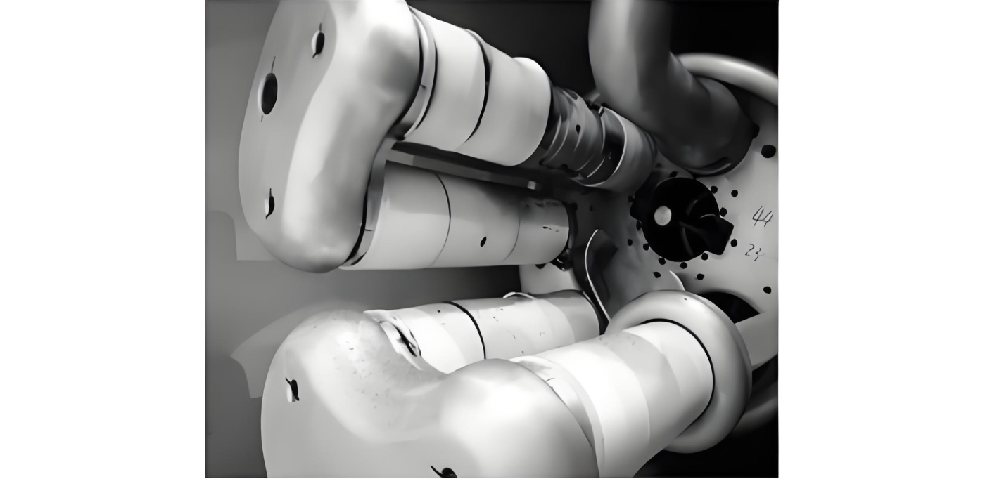
As shown in Figure 2, during the inspection of the inside of the tank during the circuit breaker dismantling process, fragments of the closing resistance and its protective sheath were observed scattered around. Some resistance chips of the fourth - column closing resistance, which was connected in parallel with the main interrupting port on the mechanism side of the circuit breaker, had exploded, and the corresponding two resistance protective sheaths had also ruptured. End shield A of the resistance showed traces of discharge ablation on the inner wall of the tank, and shield B also had traces of discharge ablation on A. In addition, the surface of the insulating support rod showed blackened traces. By checking the assembly, factory test, and on - site installation data of the circuit breaker, and inspecting the main insulating parts, no abnormalities were found.
3 Fault Cause Analysis
Through dismantling analysis, the following conclusions were drawn: During the closing process of the disconnect switch, the end shield A of the resistance first discharged to the inner wall of the tank. This led to abnormal currents in the fourth, third, and second - column closing resistances. Subsequently, shield B discharged to A, causing the second and third - column resistances to short - circuit, and the current was mainly concentrated in the fourth column. This phenomenon caused the temperature of the resistance chips in the fourth column to rise sharply, eventually leading to explosion, and the resistance protective sheath broke and fell off. During the discharge process, the generation of high - temperature arcs caused the surface of the insulating support rod to become blackened.
 
The tank - type circuit breaker can withstand a lightning impulse voltage of up to 2100kV. During the normal closing process of the disconnect switch, although over - voltage may occur, under normal operating conditions, this level of over - voltage is not sufficient to trigger the discharge mechanism of the circuit breaker. However, through in - depth analysis and inference, it is preliminarily suspected that there may be foreign objects inside the tank. These foreign objects may have an adverse impact on the electric field distribution, causing the electric field to distort and exceeding the insulation strength that the SF₆ gas gap can withstand. In this case, end shield A of the resistance may first discharge to the inner wall of the tank. Considering that the foreign objects inside the tank may be hidden in imperceptible crevices, when the disconnect switch is closed with power on, the over - voltage generated may, under the action of the electric field force, move the foreign objects to areas with a stronger electric field, thereby causing electric field distortion and leading to the occurrence of discharge phenomena.
4 Conclusion
Given the extensive application of advanced switchgear in the power system, accidents such as tripping of tank - type circuit breakers and GIS equipment due to foreign objects occur frequently. To prevent such faults, it is necessary to strengthen live - line detection work, especially increasing the detection frequency for circuit breakers that operate frequently. At the same time, during on - site acceptance, it should be strictly checked whether the equipment has completed 200 mechanical operations to ensure the running - in of the mechanism and avoid the adverse effects of metal debris on the operation of the equipment after commissioning.
 
Give a tip and encourage the author!
Recommended
10kV RMU Common Faults & Solutions Guide
Application Issues and Handling Measures for 10kV Ring Main Units (RMUs)The 10kV ring main unit (RMU) is a common electrical distribution device in urban power distribution networks, primarily used for medium-voltage power supply and distribution. During actual operation, various issues may arise. Below are common problems and corresponding corrective measures.I. Electrical Faults Internal Short Circuit or Poor WiringA short circuit or loose connection inside the RMU can lead to abnormal operati
Echo
10/20/2025
High-Voltage Circuit Breaker Types & Fault Guide
High-Voltage Circuit Breakers: Classification and Fault DiagnosisHigh-voltage circuit breakers are critical protective devices in power systems. They rapidly interrupt current when a fault occurs, preventing damage to equipment from overloads or short circuits. However, due to long-term operation and other factors, circuit breakers may develop faults that require timely diagnosis and troubleshooting.I. Classification of High-Voltage Circuit Breakers1. By Installation Location: Indoor-type: Insta
Felix Spark
10/20/2025
10 Prohibitions for Transformer Installation and Operation!
10 Prohibitions for Transformer Installation and Operation! Never install the transformer too far away—avoid placing it in remote mountains or wilderness. Excessive distance not only wastes cables and increases line losses, but also makes management and maintenance difficult. Never choose transformer capacity arbitrarily. Selecting the right capacity is essential. If the capacity is too small, the transformer may be overloaded and easily damaged—overloading beyond 30% should not exceed two hours
James
10/20/2025
How to Maintain Dry-Type Transformers Safely?
Maintenance Procedures for Dry-Type Transformers Put the standby transformer into operation, open the low-voltage side circuit breaker of the transformer to be maintained, remove the control power fuse, and hang a "DO NOT CLOSE" sign on the switch handle. Open the high-voltage side circuit breaker of the transformer under maintenance, close the grounding switch, fully discharge the transformer, lock the high-voltage cabinet, and hang a "DO NOT CLOSE" sign on the switch handle. For dry-type trans
Felix Spark
10/20/2025
Send inquiry
Download
Get the IEE Business Application
Use the IEE-Business app to find equipment, obtain solutions, connect with experts, and participate in industry collaboration anytime, anywhere—fully supporting the development of your power projects and business.