Analyse malfuctionis interruptoris SF6 in substatione 750 kV

Campus: Defectus et Manutentio
China
Donum da et auctorem hortare
Suggestus
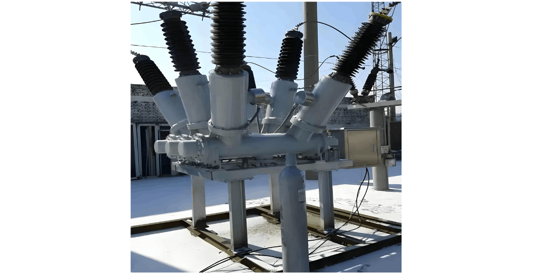
Casus Studiorum de Defectibus Installationis et Fabricationis in Isolatoribus Porcellanis Circuit-Breakerum HV 110kV
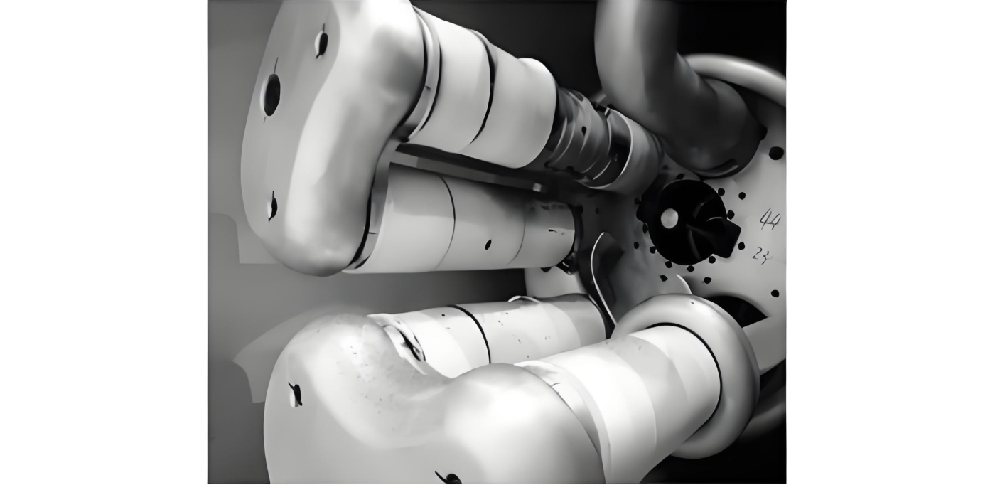
1. Fuga gas SF6 in circuito interruptore ABB LTB 72 D1 72.5 kV.Inspectio revelavit fuga gas in area contactus fixi et tegulae. Hoc factum est per incautam vel negligenter assembly, ubi anuli O bini lapsi sunt et male positi, quod cum tempore ad fuga gas duxit.2. Defectus Fabricationis in Superficie Externa Isolatorum Porcellanorum Circuiti Interruptoris 110kVEtiam si circuiti interruptores alta tensio solent protegi cum materialibus operientibus pro praeservatione isolatorum porcellanorum durant
12/16/2025
Brevis Expositio Methodorum Diagnoseos Defectuum in Interruptoribus Alternantis Tensionis Altae
1. Quae sunt parametri characteristici formae currentus spire in mechanismis operativis circuituum interruptorum altae tensionis? Quomodo huiusmodi parametri characteristici extrahuntur ex signali originali currentus spire trip?Responsum: Parametri characteristici formae currentus spire in mechanismis operativis circuituum interruptorum altae tensionis fortasse includant sequentia: Culmen currentus in statu stabilis: Valorem maximus currentus in statu stabilis in forma currentus spire electro-ma
12/16/2025
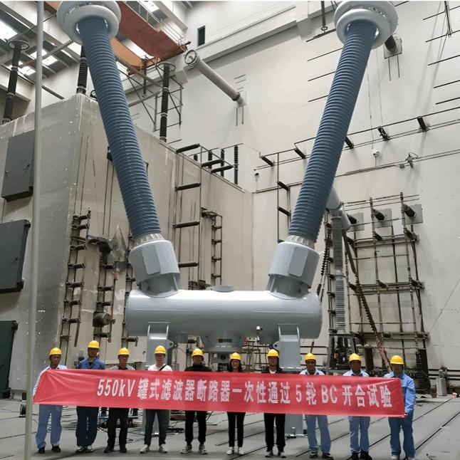
Fabricator Chinese tank-type filter recenter successus est in developmente 550 kV tank-type filter bank circuit breaker IEE-Business
Nuntius laetus venit ab uno fabricante chino de filtris cisternae: circuitus interruptor bancalis filtrorum cisternae 550 kV, quod ipse perfecit, omnes testes typi successu transivit, quod developmenti producti officio finem imponit.His annis, cum demanda electricitatis continuo crescat, retia electrica altiores exigentias performance ad apparatos electricos posuerunt. Temporibus respondentibus, fabricator chinus filtrorum cisternae activiter respondit strategiae nationali energy development, in
11/19/2025

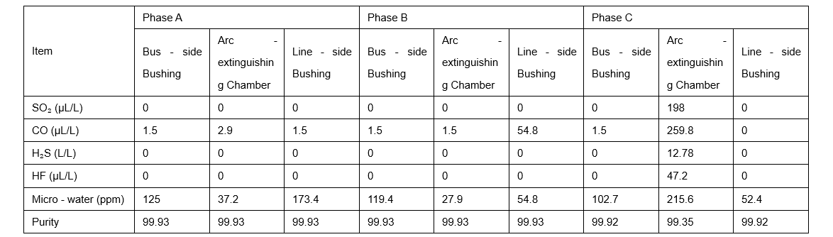
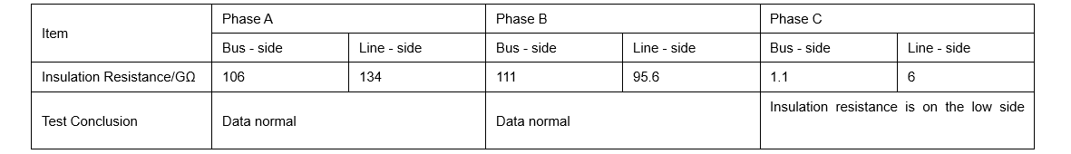
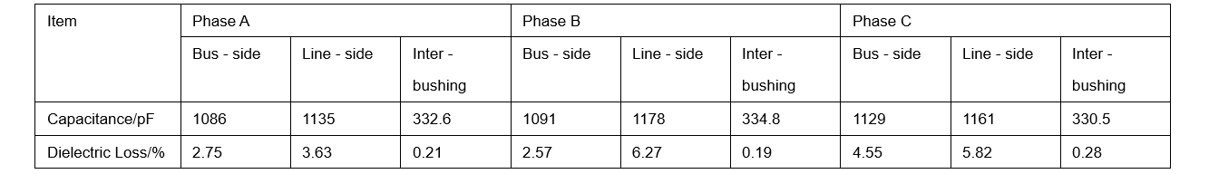
Fuga Hydraulica & Fuga Gas SF6 in Interruptoribus Circuitus
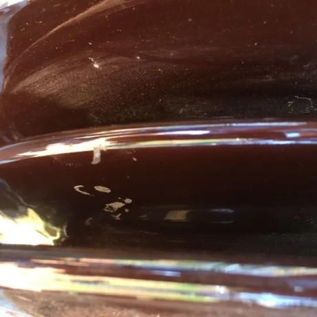
Fuga in Mechanismis Hydraulica OperativisIn mechanismis hydraulica, fuga potest causare frequentiam pumpae in brevi tempore vel tempus repressurizationis nimium longum. Fuga olei interna gravis in valvulis potest ad deficiens pressionis perducere. Si oleum hydraulicum in partem nitrogenii cylindri accumulantis intrat, potest ad pressionis augmentum anormale ducere, quod operationem securam circuitobrachiorum SF6 affectat.Praeter casus defectus aut abnormalitatis apparatorum deprehensionis pressi
10/25/2025


