Ⅰ.Maintenance Procedures for Dry-Type Transformers in India
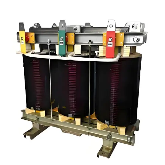
In India, with rapid urbanization and continuously growing industrial and commercial power demands, dry-type transformers are widely used in office buildings, data centers, industrial parks, and distribution networks. Due to high ambient temperatures, humidity, and significant dust levels in many regions, regular maintenance is critical to ensuring reliable transformer operation. The following outlines the standard maintenance procedures commonly adopted across India’s power systems.
First, place the standby transformer into service. Open the low-voltage side circuit breaker of the transformer to be maintained, remove the control power fuse, and hang a “DO NOT CLOSE” warning sign on the switch handle to prevent back-feeding.
Next, open the high-voltage side circuit breaker of the transformer under maintenance, close the grounding switch, and fully discharge the transformer windings to ensure the equipment is completely de-energized. Lock the high-voltage switchgear compartment and apply a safety padlock, while hanging a “DO NOT CLOSE” tag on the operating handle—complying with safety requirements under the Central Electricity Authority Regulations (CEAR).
Before beginning maintenance, clean dust and contamination from the porcelain bushings and external housing. Inspect the enclosure, gaskets, and bushings for cracks, signs of corona discharge, or aging rubber seals—issues commonly observed in India’s high-temperature environments. Also check cables and busbars for thermal deformation or loosening.
Inspect whether the busbar contact surfaces are clean. If oxidation is present, gently file the surface with a fine flat file, then apply electrical contact compound grease evenly to reduce contact resistance and prevent localized overheating—a critical step under India’s high-load operating conditions.
Check the integrity of the transformer’s grounding system and inspect grounding conductors for corrosion or breakage. In coastal cities such as Chennai or Mumbai, where salt-laden air accelerates corrosion, severely degraded grounding wires should be replaced promptly to ensure compliance with IS 3043 standards.
Tighten all terminal connections, pins, grounding screws, and busbar bolts. If any are found loose, remove the fasteners, lightly dress the contact surfaces if necessary, or replace spring washers and screws to ensure reliable electrical contact.
Clean accumulated dust from the transformer and its accessories, paying special attention to ventilation ducts to ensure unobstructed airflow. Inspect fire protection equipment (e.g., smoke detectors, fire extinguishers) and forced ventilation systems to ensure they are fully functional—this is essential for mitigating the risk of fires, a common concern in Indian electrical rooms.
After confirming safety, open the high-voltage side grounding switch, lock the high-voltage switchgear compartment, and use a 2500V megohmmeter to measure insulation resistance (phase-to-ground and phase-to-phase). The measured value should not be less than 70% of the original factory test data. If insulation resistance is low—often due to moisture ingress during monsoon seasons—immediately report the finding and take corrective actions such as drying.
Close the grounding switch again to discharge any residual charge on the transformer.
Upon completion of maintenance, inspect the transformer room and unit to ensure no tools or debris have been left behind before personnel evacuate the site.
Reinstall the control power fuse for the low-voltage side circuit breaker, but do not remove the “DO NOT CLOSE” sign yet to prevent accidental energization.
Finally, open the high-voltage side grounding switch, recheck the transformer site and low-voltage control wiring for correctness. Once confirmed, close the high-voltage side circuit breaker to energize the transformer for no-load trial operation. Monitor for abnormal noises or vibrations. After successful commissioning, remove the “DO NOT CLOSE” sign from the high-voltage side.
All maintenance steps and trial operation data must be recorded in detail and maintained as part of the maintenance log—serving as essential documentation for compliance audits in Indian factories or substations.
II. Safety Precautions (Applicable to Indian Field Operations)
Insulation resistance testing must be performed by two qualified personnel—one operating, one supervising.
Never touch any conductive parts before the transformer has been fully discharged.
Prevent back-feeding from the low-voltage side to the transformer, which could endanger personnel or damage equipment.
Maintenance personnel must wear insulating shoes and insulating gloves compliant with IS 1252 standards.
Strictly enforce the Lockout-Tagout (LOTO) procedure to prevent accidental closing of circuit breakers and ensure worker safety.
Summary
The above maintenance procedures are widely implemented across power utilities, industrial facilities, and commercial buildings in India. Adapted to local climatic conditions and regulatory standards, these practices significantly enhance the reliability and service life of dry-type transformers. Through standardized and periodic maintenance, failure rates can be greatly reduced, supporting India’s growing need for stable and uninterrupted power supply.