A Brief Discussion on the Selection of Grounding Transformers in Boost Stations
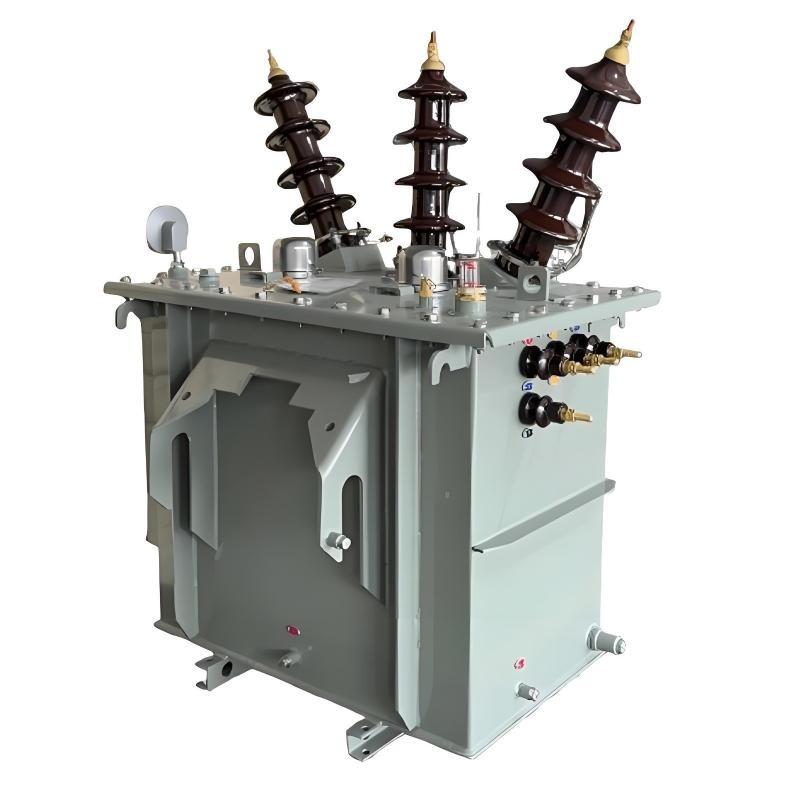
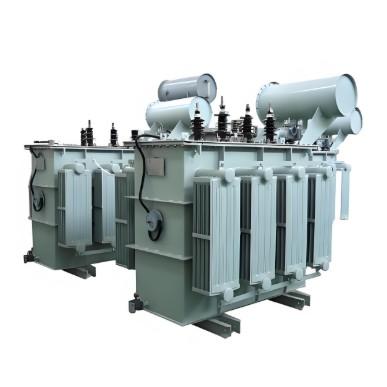
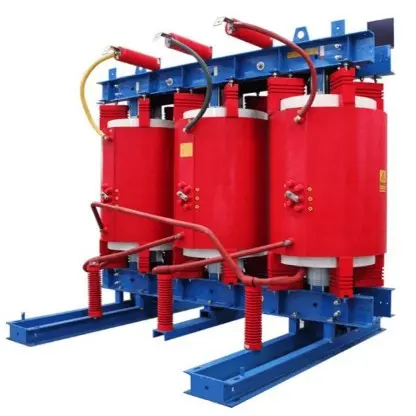
The grounding transformer, commonly referred to as "grounding transformer," operates under the condition of being no-load during normal grid operation and overloaded during short-circuit faults. According to the difference in filling medium, common types can be divided into oil-immersed and dry-type; according to phase number, they can be classified into three-phase and single-phase grounding transformers. The grounding transformer artificially creates a neutral point for connecting grounding resistors. When a ground fault occurs in the system, it exhibits high impedance to positive-sequence and negative-sequence currents, and low impedance to zero-sequence current, thereby ensuring reliable operation of the grounding protection. Proper and reasonable selection of grounding transformers is of great significance for arc extinction during short circuits, elimination of electromagnetic resonance overvoltage, and ensuring safe and stable operation of the power grid.
Selection of grounding transformers should comprehensively consider the following technical conditions: type, capacity, frequency, current and voltage, insulation level, temperature rise coefficient, and overload capability. For environmental conditions, particular attention should be paid to ambient temperature, altitude, temperature difference, pollution level, seismic intensity, wind speed, humidity, etc.
When the system neutral point can be led out, a single-phase grounding transformer is preferred; when it cannot be led out, a three-phase grounding transformer should be used.
Selection of grounding transformer capacity
The selection of grounding transformer capacity mainly considers the type of grounding transformer, the characteristics of the equipment connected to the neutral point, and whether there is a load on the secondary side. Generally, sufficient margin has already been included in the calculation of the capacity of the equipment connected to the neutral point, so no additional derating factor is required during selection.
In photovoltaic power stations, the secondary side of the grounding transformer usually carries a load. Therefore, the author briefly explains how to determine the capacity of the grounding transformer when the secondary side is loaded.
Under this condition, the capacity of the grounding transformer is primarily determined based on the capacity of the arc suppression coil connected to the transformer and the secondary load capacity, calculated according to a 2-hour rated duration equivalent to the arc suppression coil capacity. When the load is critical, the capacity can also be determined based on continuous operating time. The arc suppression coil is considered as reactive power (Qx), while the load is calculated separately as active power (Pf) and reactive power (Qf). The calculation formula is as follows:

When using grounding protection based on the reverse zero-sequence current active component, a grounding resistor with a certain resistance value is added to either the primary or secondary side of the arc suppression coil to enhance the sensitivity and accuracy of the grounding protection. Although this resistor consumes active power during operation, its usage duration is short and the resulting current increment is small; therefore, no additional capacity increase for the grounding transformer is required.