Grounding Transformer Winding Configurations
Grounding transformers are classified by winding connection into two types: ZNyn (zigzag) or YNd. Their neutral points can be connected to an arc suppression coil or a grounding resistor. Currently, the zigzag (Z-type) grounding transformer connected via an arc suppression coil or a low-value resistor is more commonly used.
1. Z-Type Grounding Transformer
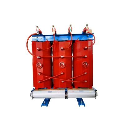
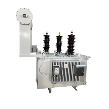
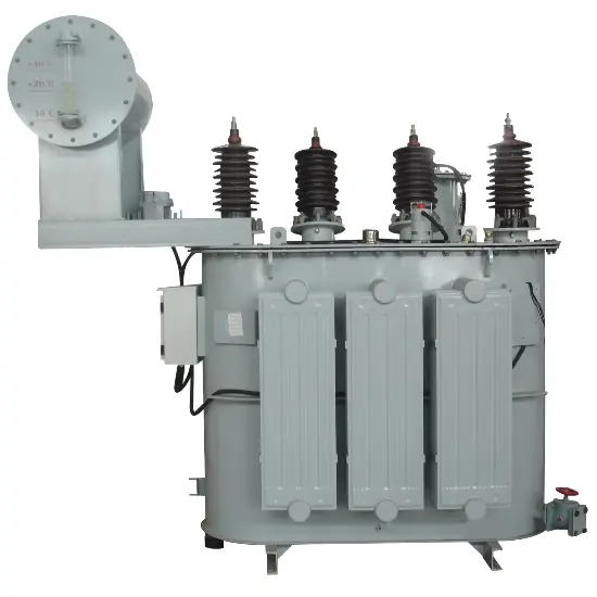
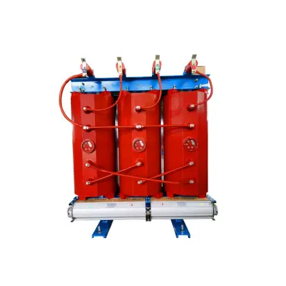
Z-type grounding transformers come in both oil-immersed and dry-type insulation versions. Among them, resin-cast is a type of dry insulation. Structurally, it is similar to a standard three-phase core-type power transformer, except that on each phase leg, the winding is split into two equal-turn sections—upper and lower. The end of one section is connected in reverse polarity series with the end of another phase’s winding.
The two winding sections have opposite polarities, forming a new phase in a zigzag configuration. The start terminals of the upper windings—U1, V1, W1—are brought out and connected to the three-phase AC supply lines A, B, and C, respectively. The start terminals of the lower windings—U2, V2, W2—are tied together to form the neutral point, which is then connected to a grounding resistor or an arc suppression coil, as shown in the figure. Depending on the specific connection method, Z-type grounding transformers are further categorized into ZNvn1 and ZNyn11 configurations.
Z-type grounding transformers may also be equipped with a low-voltage winding, typically connected in star with a grounded neutral (yn), allowing them to serve as station service transformers.

2. Z-Type Grounding Transformer
Advantages of the zigzag connection of Z-type transformers:
During a single-phase short circuit, the grounding fault current is approximately evenly distributed among the three-phase windings. The magnetomotive forces (MMFs) of the two windings on each core limb are opposite in direction, so there is no damping effect, allowing current to flow freely from the neutral point to the faulted line.
There is no third-harmonic component in the phase voltage because, in a zigzag-connected three-single-phase transformer bank, the third harmonics have identical magnitude and direction as vectors. Due to the winding arrangement, the third-harmonic electromotive forces in each phase cancel each other out, resulting in a nearly sinusoidal phase voltage.
In a Z-type grounding transformer, the zero-sequence currents in the two half-windings on the same core limb flow in opposite directions; therefore, the zero-sequence reactance is very low, and it does not choke zero-sequence current. The principle behind its low zero-sequence impedance is as follows: on each of the three core limbs of the grounding transformer, there are two windings with equal turns, each connected to different phase voltages.
When balanced positive- or negative-sequence three-phase voltages are applied to the line terminals of the grounding transformer, the MMF on each core limb is the vector sum of the MMFs from the two windings connected to different phases. The resultant MMFs on individual core limbs are displaced by 120°, forming a balanced three-phase set. The single-phase MMF can establish a magnetic circuit across all three core limbs, resulting in low magnetic reluctance, large magnetic flux, high induced EMF, and thus very high magnetizing impedance.
However, when zero-sequence voltage is applied to the three-phase line terminals, the MMFs produced by the two windings on each core limb are equal in magnitude but opposite in direction, resulting in zero net MMF per limb—hence, no zero-sequence MMF exists in the three core limbs. The zero-sequence MMF can only complete its path through the tank and surrounding medium, which presents very high magnetic reluctance; consequently, the zero-sequence MMF is very small, leading to very low zero-sequence impedance.
3.Grounding Transformer Parameters
To meet the requirements of distribution networks using arc suppression coil grounding compensation, while also satisfying the needs of station service loads for power and lighting in substations, Z-connected transformers are selected, and key parameters of the grounding transformer must be reasonably set.
3.1 Rated Capacity
The primary-side capacity of the grounding transformer should match the capacity of the arc suppression coil. Based on standard arc suppression coil capacity ratings, it is recommended that the grounding transformer capacity be set to 1.05–1.15 times the arc suppression coil capacity. For example, a 200 kVA arc suppression coil would be paired with a 215 kVA grounding transformer.
3.2 Neutral Point Compensation Current
The total current flowing through the transformer neutral point during a single-phase fault

In the above formula:
U is the line voltage of the distribution network (V);
Zx is the impedance of the arc suppression coil (Ω);
Zd is the primary zero-sequence impedance of the grounding transformer (Ω/phase);
Zs is the system impedance (Ω).
The duration of the neutral point compensation current should be the same as the continuous operating time of the arc suppression coil, which is specified as 2 hours.
3.3 Zero-Sequence Impedance
Zero-sequence impedance is a critical parameter of the grounding transformer and significantly affects relay protection settings for limiting single-phase ground fault currents and suppressing overvoltages. For zigzag (Z-type) grounding transformers without a secondary winding, as well as those with star/open-delta connections, there is only one impedance—namely, the zero-sequence impedance—enabling manufacturers to meet utility requirements.
3.4 Losses
Losses are an important performance parameter of grounding transformers. For grounding transformers equipped with a secondary winding, the no-load loss can be made equivalent to that of a two-winding transformer of the same rating. Regarding load losses, when the secondary side operates at full load, the primary side carries a relatively light load; thus, its load loss is lower than that of a two-winding transformer with the same secondary-side capacity.
3.5 Temperature Rise
According to national standards, the temperature rise of grounding transformers is regulated as follows:
The temperature rise under rated continuous current shall comply with the provisions in the national standard for general power transformers or dry-type transformers. This mainly applies to grounding transformers whose secondary side is frequently loaded.
When the short-time load current lasts no more than 10 seconds (a scenario typically occurring when the neutral point is connected to a resistor), the temperature rise shall conform to the limits specified in the national standard for power transformers under short-circuit conditions.
When the grounding transformer operates together with an arc suppression coil, its temperature rise shall comply with the temperature rise requirements for the arc suppression coil:
For windings continuously carrying rated current, the temperature rise is limited to 80 K. This primarily applies to star/open-delta connected grounding transformers.
For windings with a maximum current duration of 2 hours (as specified for the rated current), the permitted temperature rise is 100 K. This condition matches the operating mode of most grounding transformers.
For windings with a maximum current duration of 30 minutes, the permitted temperature rise is 120 K.
These provisions are based on ensuring that, under the most severe operating conditions, the hotspot temperature of the windings does not exceed 140 °C to 160 °C, thereby guaranteeing safe insulation operation and avoiding severe reduction in insulation life.