Sa mga substation, ang bilang sa mga isolating switch kadalasang duha hangtod sa apat ka beses mas dako kaysa sa mga circuit breaker. Tungod sa ilang dako nga bilang, ang gahum sa pag-install ug commissioning mahimong considerable. Para sa mga voltage level diin ang 110 kV, ang GW4-type isolating switch nagsilbi isip primary nga equipment. Kung ang pag-install ug mechanical dimensional adjustments sa isolating switch wala magmatch sa requirements, mahimo nga mag-occur ang mga problema sama sa incomplete opening/closing, overheated contacts, o padayon pa sa porcelain insulator fracture. Tungod niini, importante gyud ang pagsunod sa installation ug commissioning methods sa isolating switches. Batasan sa author’s practical experience, ang mga procedure sa installation ug commissioning para kang tipo ni isolating switch gi-summarize ania para sa reference sa mga peers.
1.Structure and Operating Principle of the GW4-Type Isolating Switch
Aron mas maayo ang pag-master sa installation techniques ug commissioning methods, importante nga adunay sufficient nga understanding sa structure ug operating principle sa switch.
1.1 Structure of the Isolating Switch
1.1.1 Structure of the Isolating Switch
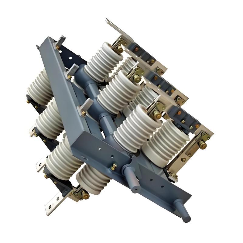
Ang GW4-type isolating switch adunay double-column horizontal rotating structure, gisulay sa tulo ka single-phase units. Kada single-phase unit adunay base, insulating columns, ug conductive parts, ug equipped sa manual o electric operating mechanisms.
1.1.2 Structure of the Earthing Switch
Ang earthing switch gisulay sa stationary contact na fixed sa conductive tube sa isolating switch ug movable contact rod na mounted sa base.
1.1.3 Structure of the Manual Operating Mechanism
Ang manual operating mechanism adunay operating handle nga nag-rotate 90° (o 180°) sa horizontal (o vertical) plane, rainproof cover, ug auxiliary switch nga nahimutang sa sulod.
1.1.4 Electric Operating Mechanism
Ang main components sa electric operating mechanism adunay electric motor, gear reducer, auxiliary switch, limit switch, selector switch, contactor, ug circuit breaker.
1.2 Operating Principle of the Isolating Switch
1.2.1 Operating Principle of the Isolating Switch
Kung ang output shaft sa operating mechanism nag-rotate 90° (o 180°), iya drive ang vertical tube → operating shaft nag-rotate 90° (o 180°) → operating crank arm → active pole sa operated phase nag-rotate 90° → horizontal linkage rod → active poles sa uban pang phases nag-rotate 90° → cross linkage rod → driven poles nag-rotate oppositely sa 90°, achieving three-pole interlocking operation.
1.2.2 Operating Principle of the Earthing Switch
Ang operating mechanism drive ang transmission shaft ug horizontal linkage rod aron mog-rotate ang rotating shaft sa earthing switch sa certain angle, thereby achieving opening o closing.
1.2.3 Operating Principle of the Manual Operating Mechanism
Kung ang handle gigamit, ang output shaft sa mechanism nag-rotate, driving ang auxiliary switch nga connected sa main shaft. Sa panahon sa opening o closing operations, ang corresponding contacts gi-open o close aron mobalhin ang respective open/close signals.
1.2.4 Operating Principle of the Electric Operating Mechanism
Ang motor start, driving ang worm gear reduction unit; ang main shaft nag-rotate, actuating ang connected isolating switch aron mo-open o close.
2.Installation of the Isolating Switch
2.1 Principles of Installation
Proper installation ug commissioning mao ang prerequisites para sa normal operation sa isolating switch. Sa usa ka sense, ang maayo nga installation mahimong half sa successful commissioning. Tungod niini, sa panahon sa installation, kinahanglan strict nga follow-on ang principle sa “level horizontally ug plumb vertically”.
(1) Ang bases sa tanang tulo ka phases kinahanglan vertically aligned—i.e., lie sa same horizontal plane—aroon mapugos ang horizontal linkage rods remain coplanar.
(2) Ang bases sa tanang tulo ka phases kinahanglan flush front-to-back—i.e., ang driven ug driving poles sa bawahan phase kinahanglan respectively lie sa same vertical plane—aroon mapugos ang horizontal linkage rods remain coplanar.
(3) Ang bases sa tanang tulo ka phases kinahanglan parallel left-to-right aron ensure proper coordination sa horizontal linkage rod lengths.
(4) Ang porcelain insulators sa tanang tulo ka phases kinahanglan perfectly vertical—aroon keep horizontal linkage rods coplanar ug ensure good contact surface alignment.
(5) Ang output shaft sa operating mechanism kinahanglan coaxial sa operating shaft sa operated phase—aroon minimize required operating torque.
2.2 Installation Requirements for Individual Components
(1) Insulating parts—kinahanglan intact ug meet specifications.
(2) Rotating (transmission) parts—kinahanglan lubricated, flexible, ug free sa binding; kon dili, apply MoS₂ o similar grease.
(3) Fixed parts—kinahanglan securely fastened without looseness.
2.3 Precautions During Installation
(1) Rated current kinahanglan comply sa design requirements.
(2) Installation direction sa earthing switch kinahanglan meet requirements. Para sa single-side earthing, mahimo left- o right-grounded; typically, ang earthing switch located sa switch side.
(3) Opening direction sa isolating switch kinahanglan meet requirements. Kung ang face sa operating mechanism, ang opening direction sa isolating switch kinahanglan align sa observer’s line of sight.
(4) Left ug right contact positions kinahanglan correctly installed: ang left contact (finger contact side) mounted sa driving pole side, ug ang right contact (contact head side) sa driven pole side.
(5) Ang main blade operating mechanism usually installed beneath ang phase A operating shaft.
(6) Phase-to-phase distance: not less than 2 m for 110 kV, ug not less than 1.2 m for 35 kV.
3.Commissioning of the Isolating Switch
3.1 Kasinatang Komisyon
Ang kasinatang komisyon mao ang pag-ila sa tanang dimensiyon ug anggulo sa mekanikal nga gipasabot aron masabtan ang mga estandar basiha sa tama ug makatarungan nga pag-install.
3.2 Proseso sa Komisyon (gikan sa baba hangtod sa taas)
3.2.1 Pag-ila sa Basehan
(1) Ila ang flatness sa basehan.
(2) Ang langit ug anggulo sa Crank Arm 1 (nagkonekta sa horizontal linkage rod) ug Crank Arm 2 (nagkonekta sa cross linkage rod) kinahanglan parehas sa tanang tatlo ka fasa. Ang Crank Arm 3 (nagkonekta sa main blade operating crank arm) nagbago batas sa manufacturer: ang uban ig-install sa base shaft (tulad sa ipakita sa Figure 1); ang uban nimo kini gi-weld sa horizontal linkage rod on-site. Kung ang dokumento sa produkto maghatag og direksyon sa pag-ila, sundon sila; kung dili, ila aron matag tubig sa koneksyon sa mechanism sa switch body, ang opening/closing angles ug synchronization maayo. (Kon ang Crank Arms 1 ug 2 gi-weld sa shaft, ang ilang anggulo ug langit dili na ma-ila.)
(3) Ila ang positioning screw aron ang clearance tali sa iya ug ang positioning stop plate adunay 1–3 mm.

3.2.2 Pag-ila sa Porcelain Insulators
Ma-ila usab pinaagi sa shims, pero butangan og atensyon kon ang thickness sa shims nga gitambong sa usa ka lugar dili mahimong mogawas sa 3 mm, ug ang tanang shims nga gitambong sa sama nga lugar kinahanglan gi-weld pinaagi sa lahi.
(1) Ang verticality sa porcelain insulators kinahanglan mosabot sa requirements.
(2) Ang taas sa duha ka porcelain insulators sa usa ka pole kinahanglan parehas.
3.2.3 Pag-ila sa Conductive Contacts
Pakalpay ang screws sa terminal block nga nag-sikuro sa conductive rod, pagkatapos ayos o shift ang conductive rod aron masabtan ang husto nga alignment.
(1) Ang duha ka conductive rods (left ug right) sa usa ka pole kinahanglan aligned—i.e., ang ilang taas kinahanglan parehas, adunay vertical height difference menor sa 5 mm, ug sila naglukso sa straight horizontal line, tulad sa ipakita sa Figure 2.
(2) Ang langit sa left ug right conductive rods sa tanang tatlo ka fasa kinahanglan parehas.
(3) Ang depth sa contact fingers sa contacts kinahanglan parehas sa tanang tatlo ka fasa. Kon ang manual sa manufacturer maghatag og numerical value, ila batas sa iyang value; kon walay value apan ang Figure 3 gibutangan, ila batas sa Figure 3; kon walay numerical value ug walay Figure 3, ila batas sa experience. Kon ang insertion labi shallow, ang contact area human sa closing dili sufficient; kon labi deep, ang excessive impact force sa closing mahimong mogubat sa insulator. Dili liwat, human sa closing, adunay clearance (margin) nga 4–6 mm kinahanglan maintindihon tali sa contact fingers ug ang contact base, ug ang insertion depth sa contact fingers sa closing dili dapat menor sa 90% sa total contact depth.

3.2.4 Pag-ila sa Operating Pole
(1) Pag-ila sa Open Distance:
Human sa isolating switch mag-open, ang anggulo tali sa conductive rod ug ang centerline sa base kinahanglan adunay 90°–92°. Kon lisod masabtan ang anggulo nga husto, usa ka simple nga paagi mao ang paggamit sa tape measure aron sukolon kon ang left ug right conductive rods parallel sa duha ka end. Usa ka difference nga ±10 mm sa distances sa duha ka end acceptable.
(2) Pag-ila Tali sa Operating Pole ug Operating Mechanism:
Ihaplot ang operating pole body ug ang mechanism sa closed position, pagkatapos konektaha (kon flexible connection). Kon rigid connection, temporary tack-weld ang joint unang (perform full welding human sa tanang adjustment kompleto). Perform usa ka complete open-close operation ug observe kon ang operating pole molambo sa full open o closed positions.
Kon ang pole dili molambo sa full closure, ila ang length sa cross linkage rod: "lengthen kon closure insufficient; shorten kon over-closed."
Kon ang pole dili molambo sa full opening, ila ang length sa operating crank arm (i.e., Crank Arm 3 sa Figure 1): "shorten kon opening angle too small; lengthen kon too large."
Note: "Shortening for insufficient opening" mahimo sa duha ka paagi: either by increasing the length of the operating crank arm or by increasing its included angle; conversely, "lengthening" mahimo sa reducing the angle or shortening the arm.
Additionally, ang angular travel sa pole body ug ang mechanism kinahanglan consistent. Dili liwat, human sa pag-ila sa operating crank arm, ang opening angle ug ang mechanism’s travel angle kinahanglan isulti-on sa samug-ano.
Kon ang pole body molambo sa proper open/closed position pero ang mechanism dili, kini nagpakita nga ang mechanism’s travel (o anggulo) menor sa body. Sa kaso ini, reduce ang required travel sa pole body pinaagi sa shortening the operating crank arm.
Conversely, kon ang mechanism molambo sa position pero ang pole body dili, lengthen the operating crank arm.
3.2.5 Three-Pole Interlocking Adjustment
Ang three-pole interlocking adjustment kinahanglan perform under the condition nga tanang terminal plates sa isolating switch adunay normal busbar tension. Kon dili, re-adjustment kinahanglan human sa busbars konektado.
Human sa operating pole (e.g., Phase A) properly adjusted, ihaplot ang tanang tres ka poles sa closed position, install ang horizontal linkage rods, ug perform usa ka full open-close cycle. Observe kon ang uban duha ka poles molambo sa proper open/closed positions.
Ang pamantayan sa pag-synchronize sa tig-tatlo nga polo batasado gikan sa parehas nga pag-engage sa mga contact. Sa panahon sa pag-adjust, kung ang contact sa bisan asa ka polo na lang mohitabo sa iyang contact finger, sukdi ang mga gap sa pagitan sa mga contact ug contact fingers sa uban pang duha ka polo, ug i-adjust kini nga mga gap pinaagi sa pag-usab sa length sa cross linkage rods.
Kon human natuman ang synchronization, pero ang open/close positions wala pa gihapon maabot, gamiton ang “compromise method”: kuhaa ang midpoint sa over-travel ug under-travel values ug i-adjust padulong sa kini nga median—sa siguro nga mosunod sa specified synchronization tolerance sa manufacturer.
Common scenarios (assuming Phase A is the operating pole):
(1) Tanang tig-tatlo nga polo synchronized pero wala pa maabot ang full open/close position → slightly adjust the operating crank arm length.
(2) Tanang tig-tatlo nga polo nakaabot sa proper open/close positions pero out of sync → use the compromise method on cross linkage rods to meet synchronization standards.
(3) Ang Phases A ug B synchronized, pero ang Phase C dili pa (pero tanan operate correctly) → adjust Phase C’s cross linkage rod.
(4) Ang Phases B ug C synchronized, pero ang Phase A dili pa → adjust Phase A’s cross linkage rod.
(5) Ang Phases A ug C synchronized, pero ang Phase B dili pa → adjust Phase B’s cross linkage rod.
(6) Tanang tig-tatlo nga polo synchronized, pero ang Phases A ug B wala pa maabot ang fully closed/open position → either adjust the horizontal linkage rod between Phases A and B to bring them into proper position, or adjust Phase C’s cross linkage rod so that its incomplete travel matches that of Phases A and B, then readjust the operating crank arm length.
(7) Tanang tig-tatlo nga polo synchronized, pero ang Phases B ug C wala pa maabot ang fully closed/open position → adjust the horizontal linkage rod between Phases B and C, or adjust Phase A’s cross linkage rod to match the incomplete travel of Phases B and C, then adjust the crank arm length.
(8) Tanang tig-tatlo nga polo synchronized, pero ang Phases A ug C wala pa maabot ang fully closed/open position → adjust both the AB and BC horizontal linkage rods, or adjust Phase B’s cross linkage rod to match the incomplete travel of Phases A and C, then adjust the crank arm length.
(9) Worst-case scenario: tanang tig-tatlo nga polo out of synchronization ug incomplete travel → comprehensively adjust the horizontal linkages, cross linkages, and the operating crank arm using the compromise method to meet the required specifications.
Thus, ang principle sa three-pole interlocking adjustment mao ang: synchronization must meet specifications, closing must be precise, ug opening must satisfy the required contact gap distance. Generally, kon mag-encounter og conflicts ang tulo ka criteria, ang opening contact gap takes priority, ug minor sacrifice of opening distance may be acceptable if needed.
(Note: For cross and horizontal linkage rods with opposite-threaded ends, try to keep the exposed thread lengths equal on both sides during adjustment.)
3.2.6 Adjustment of Open/Close Positioning Screws
Human natuman ang three-pole interlocking adjustment, tighten the lock nuts on the cross and horizontal linkage rods. Then adjust the clearance between the open/close positioning screws and the stop plate to 1–3 mm.
3.3 Commissioning of the Earthing Switch
Ang commissioning sa earthing switch mahimong gibuhat human natuman ang full commissioning sa main isolating switch. Ang method similar, pero ang sumala nga puntos adunay kinahanglanon nga atensyon:
(1) Ang horizontal linkage rods sa earthing switch mostly connected via pipe clamps. Therefore, when tightening bolts, apply torque crosswise, symmetrically, evenly, and gradually; otherwise, misalignment may occur between the earthing conductive rod and the stationary contact.
(2) Contact between the earthing conductive rod and the stationary contact must be good. Ideally, the conductive rod should protrude 3–10 mm beyond the stationary contact—though specific values vary by manufacturer and should follow the manual. Generally, since the main switch’s horizontal linkage is installed on the driving pole side, for an internal-type earthing switch with right-side grounding, the protrusion should not be excessive; otherwise, when the main isolating switch is open, the earthing blade may fail to close due to mechanical interference between the earthing rod tip and the main switch’s horizontal linkage.
(3) In the open position, the earthing conductive rod should remain horizontal. Use a spirit level if necessary to ensure the required insulation distance is maintained after opening.
3.4 Mechanical Interlock Adjustment
Human natuman ang commissioning sa isolating switch ug earthing switch, adjust the mechanical interlock—this marks the completion of the entire isolating switch group commissioning.
Adjust the relative position of the sector plate and arc-shaped plate on the base so that:
When the isolating switch is closed, the earthing switch cannot be closed;
When the earthing switch is closed, the isolating switch cannot be closed.
3.5 Commissioning of Manual Operating Mechanism
Ang manual operating mechanism adjusted concurrently with the main body. During adjustment, also verify:
(1) Smooth rotation of the mechanism—operating force on the handle should not exceed 1 kgf.
(2) Correct switching of the auxiliary switch—the standard is that the auxiliary switch reliably operates at approximately 4/5 of the travel toward the limit position during mechanism movement.
3.6 Commissioning of Electric Operating Mechanism
Ang commissioning sa electric mechanism mas komplikado kaysa sa manual type. Key inspection items include:
(1) Tanan nga mga komponente ay kompleto.
(2) Ang pagkakawire ay tama; gibuhat ang daghang manual/electrik ug lokal/remote nga operasyon aron matiyakan ang hustong pag-act.
(3) Sa wala pa ibuto sa energy para sa test operation, isulod ang mekanismo sa mid-position sa pagitan sa open ug closed, pagkatapos operasyon.
(4) Ang direksyon sa pag-rotate sa motor mahimong sama sa gikinahanglan nga open/close direction sa main body.
(5) Ang tanang elektrikal ug mekanikal nga limit switches kinahanglan ma-adjust ug ma-align sa final open/close positions sa main body.
4.Pagwagtug
Tungod kay ang isolating switches adunay dugang kaayo nga panahon nga gisulti nga simple nga elektrikal nga mga device, ang mga operational defects sama sa mechanical binding ug overheating sa conductive circuit madalas magamit, kasagaran nagpuwang sa unplanned outages ug seriosong naaapektuhan ang reliability sa power supply.
Ang pagka-familiar sa structure, operating principles, ug installation/commissioning methods sa isolating switches makapadaghan sa pag-prevent sa forced outages ug unreliable operations, makapadaghan sa efficiency sa on-site nga trabaho, ug makatubag sa contradiction sa pag-una nga dili reliable ang performance sa equipment ug ang taas nga gikinahanglan nga reliability sa modern nga power systems.