Optimized Guide to Transformer Fault Diagnosis and Advanced Testing Techniques
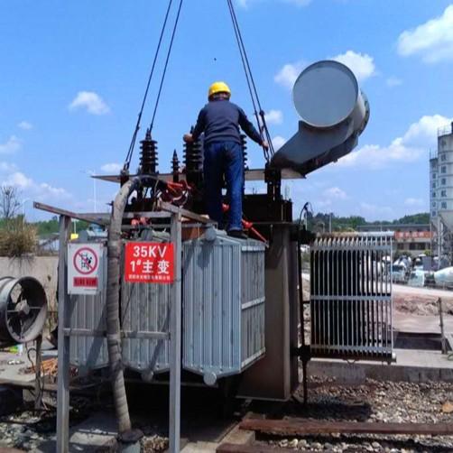
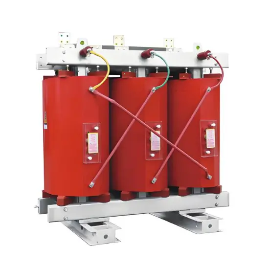
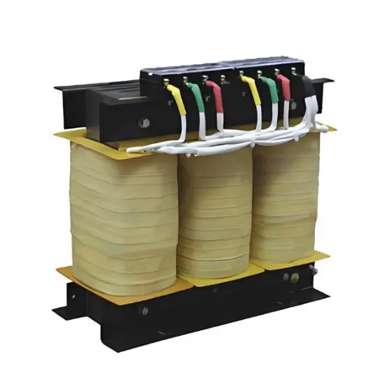
Transformers are core components in power systems, and their operational reliability directly impacts power supply safety. Common types include oil-immersed and dry-type transformers. Failures typically occur in the windings, core, connections, and insulation oil, with typical issues such as inter-turn short circuits, insulation aging, overheated joints, and multi-point core grounding.
1. Common Fault Indicators
Immediate attention is required if a transformer exhibits any of the following symptoms:
Severe overheating or abnormal temperature rise
Unusual noises (e.g., humming, arcing)
Three-phase voltage/current imbalance
Darkened oil color, acidic odor, or sludge formation
Frequent protective relay operations or tripping
2. Routine Maintenance Items
To ensure long-term stable operation, the following basic tests should be performed regularly:
| Test Item | Purpose | Common Method |
| Insulation Resistance Test | Assess overall insulation condition | Use megohmmeter to measure R60s, R15s; calculate Dielectric Absorption Ratio (DAR) and Polarization Index (PI) |
| DC Resistance Test | Check winding integrity and connections | Micro-ohmmeter measures DC resistance per phase to detect turn-to-turn shorts or poor contacts |
| No-Load Test | Evaluate core performance and losses | Measure no-load current and no-load losses |
| Core Lifting Inspection | Full internal inspection (during major overhaul) | Visual check for winding deformation, insulation damage, loose core |
| Oil Quality Test (oil-immersed) | Assess insulation oil aging | Includes physicochemical analysis and Dissolved Gas Analysis (DGA) |
3. Advanced Diagnostic Techniques
3.1 ALL-Test – Comprehensive Winding Condition Assessment
Principle
Uses high-frequency, low-voltage signals (not high voltage) to excite windings and measure key parameters:
DC Resistance (R)
Impedance (Z)
Inductance (L)
Phase Angle Tangent (tgφ)
Current-to-Frequency Ratio (I/F)
Multi-parameter analysis enables high-sensitivity detection of early winding defects.
Non-destructive: Low-voltage testing avoids aggravating existing flaws;
High Precision: Resolution up to 0.001Ω, capable of detecting minor inter-turn faults;
Fast On-Site Diagnosis: Internal condition assessed without core lifting;
Trend-Based Monitoring: Data can be stored and trended for predictive maintenance;
Multi-Parameter Cross-Validation: Enhances diagnostic accuracy through parameter correlation.
| Parameter | Normal Range | Warning Level | Failure Indication |
| R (DC Resistance) | Phase difference ≤5% (R>0.25Ω)≤7.5% (R≤0.2Ω) | Exceeds above limits | Inter-turn short, poor contact |
| Z (Impedance) | Phase difference ≤5% | >5% | Winding deformation/displacement |
| L (Inductance) | Phase difference ≤5% | >5% | Magnetic circuit fault, shorted turns |
| tgφ (Phase Angle) | Phase difference ≤1 digit (e.g., 0.1 vs 0.2) | ≥0.2 difference | Insulation degradation |
| I/F (Current/Freq Ratio) | Phase difference ≤2 digits (e.g., 1.23 vs 1.25) | >0.03 difference | Winding inconsistency or local short |
3.2 Case Comparison
| Test Parameter | Healthy Transformer (2500kVA) | Faulty Transformer (500kVA) |
| R (Ω) | 0.096–0.103 | 48.5–116.1 (severe imbalance) |
| Z (Ω) | 14–15 | 1406–4972 (H₁-H₂ abnormal) |
| L (mH) | 2 | 2237–7911 (H₁-H₂ significantly high) |
| Conclusion | Healthy condition | Severe inter-turn short or open circuit in H₁-H₂ phase |
3.3 Turns Ratio Test (TTR)
Verifies actual turns ratio against nameplate value to detect:
Inter-turn short circuits
Open circuits
Wiring errors
Winding deformation
Deviation > ±0.5%: Requires further investigation;
Unbalanced three-phase ratios: Indicates localized damage;
No reading: Possible severe short or open circuit.
Use dedicated TTR tester (accuracy ≥0.1%);
De-energize and discharge fully before test;
Record all three phases and compare historically.
3.4 Transformer Oil Quality Testing
For oil-immersed transformers, insulating oil acts as the "lifeblood" — its condition reflects overall equipment health.
| Parameter | New Oil Standard | In-Service Oil Standard | Test Method |
| Water-Soluble Acid (pH) | >5.4 | ≥4.2 | GB7598 |
| Acid Value (mgKOH/g) | ≤0.03 | ≤0.1 | GB7599 / GB264 |
| Flash Point (Closed Cup, °C) | >140 、>135 | Not <5°C below new oil value | GB261 |
| Mechanical Impurities | None | None | Visual |
| Free Carbon | None | None | Visual |
Gas chromatography analyzes types and concentrations of dissolved gases in oil to identify fault type and severity — even while energized.
| Fault Type | Primary Gases | Secondary Gases |
| Localized Overheating (<300°C) | CH₄, C₂H₆ | CO, CO₂ |
| Severe Overheating (>700°C) | C₂H₄, H₂ | CH₄, C₂H₆ |
| Partial Discharge | H₂, CH₄ | Trace C₂H₂ |
| Arcing | C₂H₂, H₂ | C₂H₄, CH₄ |
| Moisture/Decomposition | H₂ (significantly elevated) | — |
| Gas | Normal | Caution | Fault |
| Total Combustible Gases | <0.1% | 0.1%–0.5% | >0.5% |
| H₂ (Hydrogen) | <0.01% | 0.01%–0.02% | >0.02% |
| C₂H₂ (Acetylene) | <0.0005% | — | >0.001% |
4.2 Recommended Integrated Diagnostic Strategy
| Method | Application | Advantage | Suggested Frequency |
| ALL-Test | Rapid winding assessment | High sensitivity, non-invasive | Critical units: Monthly |
| Turns Ratio Test | Post-installation / overhaul | Fast detection of wiring errors | After commissioning, after major repair |
| Oil Testing | Routine maintenance (oil-filled) | Comprehensive oil health check | Every 6 months |
| DGA | Early warning & precision diagnosis | “Gold standard” for incipient faults | Every 3–6 months; more frequent if abnormal |
5. Summary & Recommendations
Prevention over Repair: Establish regular testing schedules to prevent unexpected failures;
Multi-Method Integration: Combine ALL-Test, DGA, and TTR for cross-validated, reliable diagnosis;
Data-Driven Decisions: Maintain equipment health records and monitor parameter trends;
Smart Upgrades: Consider online monitoring (e.g., continuous DGA, temperature sensors) for predictive maintenance;
Personnel Training: Ensure staff understand basic criteria and emergency response procedures.