
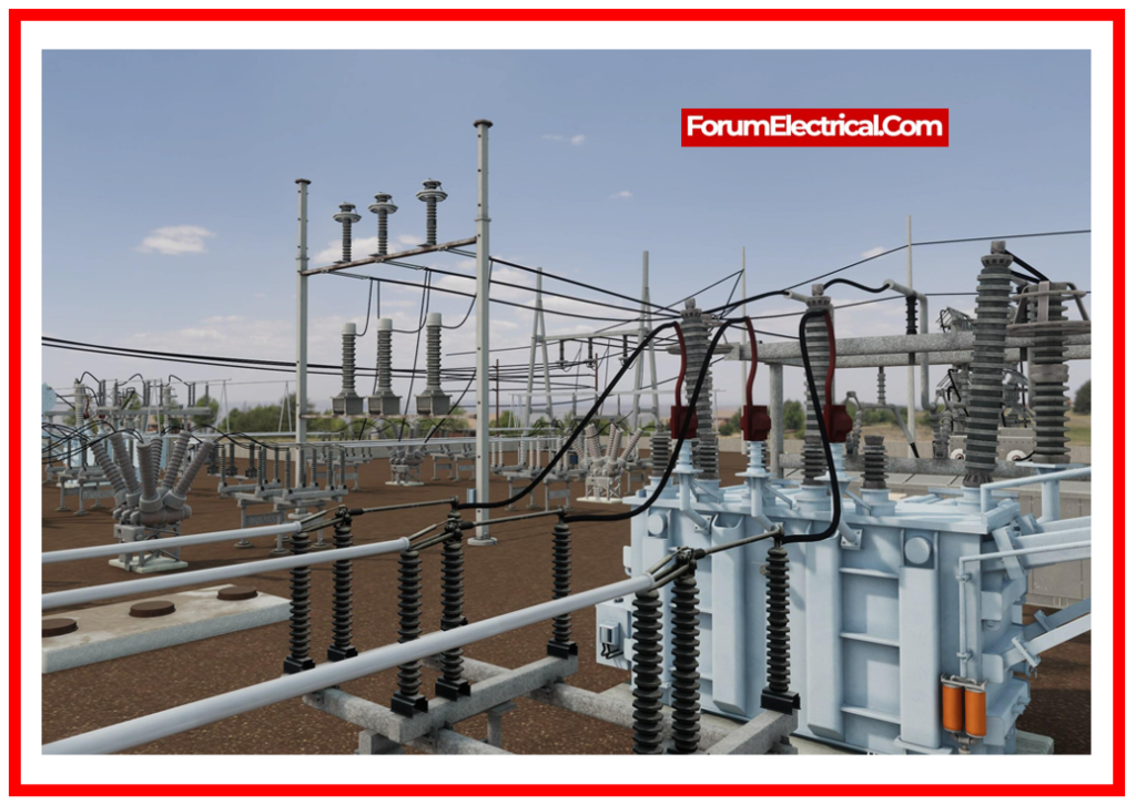
Electrical substations constitute essential sections of the power distribution network, functioning as hubs for transmitting & distributing electricity. These complex facilities necessitate rigorous planning, design, & implementation to assure a consistent and efficient power supply.
In this post, we will look at the foundations of electrical substation design, including different components, layout concerns, and environmental factors.
The maximum fault level on a new substation bus cannot be more than 80% of the circuit breaker’s rated rupturing capacity.
The 20% buffer is meant to account for the increase in the short circuit levels as the system development.

The rate of breaking current and generating current, as well as the fault clearing time capabilities of switch gear at the different voltage levels, can be calculated as:
| Fault clearing Time | Voltage level | Operating Time | Breaking current | Acking current |
| 150 ms | 33 kV | 60-80 ms | 25 KA | 62.5 KA |
| 120 ms | 132 kV | 50 ms | 25/31.5 KA | 70 KA |
| 100 ms | 220 kV | 50 ms | 31.5/40 KA | 100 KA |
| 100 ms | 400 kV | 40 ms | 40 KA | 100 KA |
The capacity of any single substation at various voltage levels should not generally exceed.
| Sub-Station | Voltage Level |
| 765 KV | 2500 MVA |
| 400 KV | 1000 MVA |
| 220 KV | 320 MVA |
| 110 KV | 150 MVA |
The size & number of interconnecting Transformers (ICTs) must be planned in such a way that the failure of any single unit does not overload the remaining ICTs or underlying system.
A stuck breaker cannot interrupt more than 4 feeders for a 220 KV system, two for a 400 KV system, and one for a 765 KV system.
| S.No | Technical Parameter Description | Units | System | |||||
| 1 | System Nominal Voltage | kVrms | 400 kV | 220 kV | 132 kV | 33 kV | ||
| 2 | System Maximum Voltage | kVrms | 420 kV | 245 kV | 145 kV | 36 kV | ||
| 3 | Power frequency withstand voltage | kVrms | 630 kV | 460 kV | 275 kV | 70 kV | ||
| 520 kV | ||||||||
| 4 | Switching surge withstand voltage | kVp | ||||||
| (for 250/2500ms) | ||||||||
| 1). Line-to-Earth | 1050 kVp | Not | Not | Not | ||||
| 2). Across Isolating Gap | 900kVp+345kVrms | applicable | applicable | applicable | ||||
| 5 | Lightning Impulse Withstand Voltage | kVp for 1.2/50(ms) | ||||||
| 1). Line-to-Earth | 1425 kVp | 1050 kVp | 650 kVp | 170 kVp | ||||
| 2). Across isolating gap | 1425 kVp+ 240kVrms | 1200 kVp | 750 kVp | 195 kVp | ||||
| 6 | One minute power frequency withstand value | |||||||
| Dry | ||||||||
| Wet | kVrms | 520 | 460 | 275 | 70 | |||
| kVrms | 610 | 530 | 315 | 80 | ||||
| 7 | System frequency | Hz | 50 | |||||
| 8 | Variation in frequency | % | 2.5 | |||||
| 9 | Corona extinction voltage | 320 kV | 156 kV | 84 kV | ||||
| 10 | Radio interference voltage | 1000 mV at | 1000 mV | 1000 mV at | ||||
| 266 kV | at 167 kV | 93 kV | ||||||
| 11 | System Neutral rating | Solidly earthed | ||||||
| 12 | Continuous Current Rating | 1600 A (or) 2000 A | 1600 A | 800 A | 600 A | |||
| 13 | Symmetrical fault current (ISC) | kA | 40 | 40 | 31.5 | 25 | ||
| 14 | Short circuit fault current duration | Second | 1 | 1 | 1 | 3 | ||
| 15 | Dynamic short circuit (ISC) current rating | kAp | 100 kA | 100 kA | 79 kA | 62.5kA | ||
| 16 | Conductor spacing for AIS layouts (Phase-to-Ground) | meter | ||||||
| Phase-to-Phase | meter | 6.5 | 4.5 | 3 | 1.5 | |||
| 7 | 4.5 | 3 | 1.5 | |||||
| 17 | Design ambient temperatures | oC | 50 | |||||
| 18 | Pollution level as per IEC-815 & 71 | III | ||||||
| 19 | Creepage -Distance | mm | 10500 mm | 6125 mm | 3625 mm | 900 mm | ||
| 20 | Maximum fault clearing time | ms | <100 | <100ms | <150ms | |||
| 21 | Bay Width | meter | 27 | 16.4-18 | 10.4.12.0 | 5.5 | ||
| 22 | Bus equipment interconnection height from ground | meter | 8 | 5.5 | 5 | 4 | ||
| 23 | Strung busbar height | meter | >15 | 10 | 8 | 5.5 | ||
Reliability: The reliability of the power system is the uninterrupted supply of power at the required voltage and frequency. Busbars, circuit breakers, transformers, isolators, and regulating devices affect substation reliability.
Failure Rate: It is the annual failure average.
Outage Time: Outage time refers to the time required to fix a failing component or switch to a different supply source.
Switching Time: Time from outage start to service restoration via switching operation.
Switching Scheme: The placement of bus bars & equipment takes into account cost, flexibility, and system reliability.
Phase-to-Ground Clearance: Substation phase to ground clearance is
Distance between conductor & structure.
Distance between live equipment and structures &
Distance between live conductor and earth.
Phase-to-Phase Clearance: Substation phase-to-phase clearances are
Distance between live conductors.
Distance between live conductors & apparatus and
Distance between live terminals in circuit breakers, isolators, etc.
Ground Clearance: It is the minimum clearance from any location where a human may need to stand to the nearest non-earth potential part of an insulator supporting the live conductor.
Sectional Clearance: It is the minimum clearance from any standing location to the nearest unscreened live conductor. Take the height of a guy with stretched hands and the phase-to-ground clearance to calculate sectional clearance.
Safety Clearance: This includes ground and sectional clearance.
Substation Electrostatic Field: Energized conductors or metallic parts create electrostatic fields. EHV substations (over 400 KV) have electrostatic fields that vary depending on the geometry of the energized conductor/metallic portion and the neighboring earthed object or ground.
Transmission lines,
Sub-transmission feeders,
Generating circuits, and
Step-up and step-down transformers
connect to substations or switching stations.
Substations from 66 to 40 KV are called EHV. Above 500KV, they’re UHV.
The design concerns and methods for EHV substations are similar, however some elements dominate at various voltage levels. Up to 220 KV, switching surges can be ignored, but over 345 KV, they are essential.
Substation design requirements will be determined by the following studies.
Load Flow Studies
Short Circuit Studies
Transient Stability Studies
Transient Overvoltage Studies
A substation ensures reliable power transmission to system loads.
The current carrying needs of the new substation (or) switching station are determined by load flow studies while all lines are in & while selected lines are out for maintenance.
After evaluating several load flow conditions, equipment continues & emergency ratings can be calculated.
In addition to continuous current ratings, substation equipment needs to have short time ratings.
These must be sufficient to enable the equipment to withstand short circuit current heat and mechanical pressures without damage.
To provide adequate interrupting capability in breakers, strength in post insulators, and appropriate setting for protective relays that sense the fault.
The maximum & minimum short circuit currents for various types and locations of short circuits and system configurations must be established.
Normal generator mechanical input equals electrical output in addition to generator losses.
System generators revolve at 50 Hz as long as this continues. Any disturbance in mechanical or electrical flow causes the generator speed to depart from 50Hz and oscillate around a new equilibrium point.
A highly common disturbance is short circuit. Short circuits near the generator lower terminal voltage and speed the machine.
After fixing the error, the device will feed excess energy into power system to restore its original state.
When electrical links are strong, the machine decelerates fast and stabilizes. Weak ties will cause machine instability.
Factors affecting stability include:
Fault severity,
Fault clearance speed,
Links between machine and system following fault resolution.
Substation transient stability depends on
Line and bus protection relaying type and speed,
Breaker interrupting time, and
Bus configuration once the fault is cleared.
The last point affects bus arrangement.
Only one line will be affected if a fault gets resolved during primary relaying.
A blocked breaker may cause multiple lines to be lost during breaker failure relaying, weakening the system tie.
Transient overvoltage can result from lightning or circuit switching.
Transient Network Analyzer (TNA) studies are the most accurate way to determine switching over voltage.

Substation Arrangement Layout
The substation arrangement is determined by physical and electrical considerations, including the following:
Systems Security
Operations Flexibility
Easy Protection Arrangements
Limiting Short Circuit Levels
Maintenance Facilities
Easy Extension
Site Factors
Economy
Ideal sub-stations include separate breakers for each circuit and allow for replacement of bus-bars or breakers during maintenance or faults.
System security can be determined by allowing 100% dependence on substation integrity or allowing a percentage of downtime due to periodic faults (or) maintenance.
Although a double bus-bar system with the double breaker design is perfect, it is an expensive substation.
Controlling MVA & MVAR loading under all circuit connection conditions is essential for generator loading efficiency.
Load circuits must be grouped to provide optimal control in normal and emergency conditions.
If one circuit breaker controls many circuits or more circuit breakers are broken. This can be mitigated by bus sectionalism.
Even if protective relaying is simple, a single bus system is rigid for complicated protection.
A substation can be divided into two portions, either entirely or through reactor connection, to reduce short circuit levels.
Proper usage of circuit breakers in the ring systems can provide a similar facility.
Maintenance is required during substation operation, either planned (or) emergency.
The performance of the substation while maintenance depends on the protection provisions.
The substation layout should allow for bay extension for new feeders.
As the system improves, it may be necessary to switch from a single bus arrangement to a double bus system or enlarge a mesh station to a double bus station.
Space and expansion facilities will be available.
Site availability is essential for substation planning. Construction of a station with less flexibility can be necessary in limited places.
The substation with fewer breakers and a simpler schematic occupies less space.
If economics are feasible, an improved switching arrangement for technological requirements can be created.
Substation layout & switching arrangement must be carefully designed based on IEEE 141 to ensure electrical distribution system efficiency and safety.
Transformers,
Circuit breakers, and
Switches
must be chosen based on voltage and load requirements.
To maximize space, ease maintenance, and allow extension, the layout has to be carefully planned. Busbars should efficiently link equipment, and circuits should improve power flow & reliability.
For fast fault detection and isolation, robust protection & control systems are needed. Regulatory standards & environmental concerns determine substation design to ensure safety, dependability, and environmental compliance.
Several aspects should be considered while designing an EHV layout and switching configurations:
It should be reliable, secure, and ensure excellent service continuity.
Typical substation busbar schemes and protection are explained as detailed in:
What is Electrical Busbar? Types, Advantages, Disadvantages &
Busbar Protection Schemes
Different busbar configurations provide different advantages in terms of redundancy, operating flexibility, and maintenance accessibility.
Efficient busbar layout makes sure efficient power flow & facilitates future expansion.
Structures are needed to support & install bus electrical equipment and terminate transmission line cables.
Structures can be made of steel, wood, RCC, or PSC. Based on side soil, they need foundations.
Substations use fabricated steel constructions for their advantages.
The
Phase clearance,
Ground clearance,
Insulators,
Bus length, and
Equipment weight
effect structural design.
Bending,
Flange buckling,
Vertical and horizontal shear, and
Web crippling
must prevent steel beam and girder failure.
Lattice box girders should be 1/10 to 1/15 of the span & square. Usually, beam defluxion cannot exceed 1/250 of span length.
Structure bolts and nuts must be 16 mm in diameter, except in light-loaded sections where they can be 12 mm.
The design load for columns and girders should comprise
Conductor tension,
Earth wire tension,
Insulator and hardware weight, and
Fraction load (about 350 kg),
Worker and tool weight (200 kg)
Wind and impact loads
during equipment operation.
The overhead line download span must be terminated by the substation gantry structures. it can go up to +15 degrees vertically and +30 degrees horizontally.
The yard structures can be painted or hot dip galvanized.
Structures made with galvanized steel require minimal upkeep.
However, painted structures provided better corrosion resistance in some extremely contaminated areas.
Normally employed phase spacings as:
| 11 KV | 1.3 m |
| 33 KV | 1.5 m |
| 66 KV | 2.0 to 2.2 m |
| 110 KV | 2.4 to 3 m |
| 220 KV | 4.5 m |
| 400 KV | 7.0 m |
In order to facilitate the connection between the many components that comprise of a substation, busbars are conductive bars that are used for transmitting electrical power throughout the substation.
Electrical losses are reduced, power distribution is made more consistent, and substation performance is improved when busbars are designed and sized correctly.
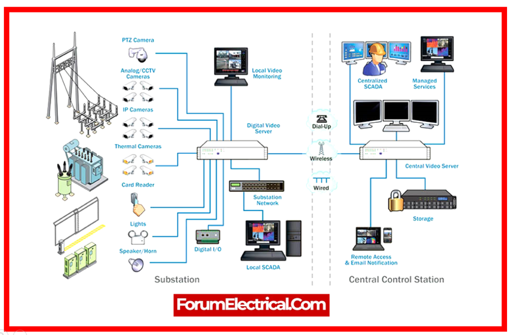
Substation automation optimizes operation and efficiency by combining control systems, intelligent devices, & communication networks.
Real-time monitoring, remote control, data analysis, & predictive maintenance improve reliability and reduce downtime with automation.
Advanced control systems like SCADA improve substation automation, data collection, & remote control.
Substation automation utilizes SCADA systems for centralized control and monitoring.
SCADA systems collect substation data to enhance power flow, make decisions, and resolve faults quickly.

Substation design architecture requires dependable communication protocols like IEC 61850, DNP3, or Modbus for interoperability, data integrity, & cybersecurity.
Statement: Respect the original, good articles worth sharing, if there is infringement please contact delete.


