Transformer Bushings: Function, Types & Installation Guide

Transformer Bushings: External Insulation and Current-Carrying Components
Transformer bushings are the primary external insulation devices mounted on the transformer tank. The leads from the transformer windings must pass through these insulating bushings, which provide insulation between the leads as well as between the leads and the transformer tank, while also serving to mechanically secure the leads.
Depending on the voltage level, transformer bushings are available in several types: porcelain bushings, oil-filled bushings, and capacitor-type bushings.
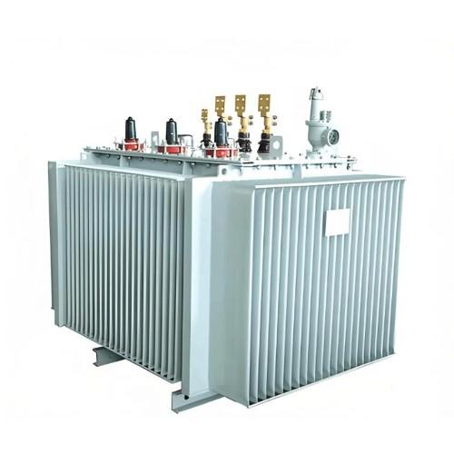
Porcelain bushings are commonly used in transformers rated 10 kV and below. They consist of a conductive copper rod passing through a porcelain housing, with air providing the internal insulation.
Oil-filled bushings are typically used in 35 kV-class transformers. These bushings are filled with insulating oil inside the porcelain housing, through which a copper conductor passes, insulated with oil-impregnated paper.
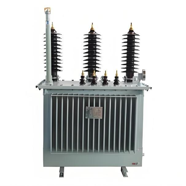
Capacitor-type bushings are used in high-voltage transformers above 100 kV. They consist of a main insulation unit (capacitor core), upper and lower porcelain housings, a connecting sleeve, oil reservoir (conservator), spring assembly, base, grading ring (corona shield), measuring terminal, line terminal, rubber gaskets, and insulating oil.
Transformer bushings serve to bring the internal high-voltage and low-voltage winding leads out of the oil tank. They not only provide insulation between the leads and ground but also play a critical role in securing the leads. As one of the current-carrying components of the transformer, bushings carry load current continuously during normal operation and must withstand short-circuit current during external faults.

Therefore, the following requirements apply to transformer bushings:
Must have specified electrical insulation strength and sufficient mechanical strength.
Must exhibit good thermal stability and be capable of withstanding momentary overheating during short-circuit conditions.
Should have compact size, light weight, excellent sealing performance, high interchangeability, and ease of maintenance.
The bushing is mainly composed of a capacitor core, oil reservoir, flange, and upper/lower porcelain housings. The main insulation is the capacitor core, formed by concentric capacitive layers connected in series. This assembly is enclosed within a sealed chamber formed by the upper and lower porcelain housings, oil reservoir, flange, and base. The chamber is filled with treated transformer oil, resulting in an oil-paper insulation structure. Oil-resistant rubber gaskets are used at contact surfaces between major components. All components are compressed together by a central preloading force applied via a set of strong springs located in the oil reservoir, ensuring the entire bushing remains hermetically sealed.
The flange is equipped with an air vent plug, oil sampling device, and terminals for measuring dielectric loss (tan δ) and partial discharge (PD). During operation, the protective cover of the measuring terminal must be installed to ensure reliable grounding of the screen (test tap); open-circuit conditions are strictly prohibited.
There are two main connection methods between the bushing and the high-voltage leads of the transformer:
Cable-penetration type
Conductor-rod current-carrying type
Pre-Installation Inspection of Transformer Bushings:
Before installation, the following checks should be performed:
Check the porcelain surface for cracks or damage.
Ensure the inner surfaces of the flange neck and grading ring are thoroughly cleaned.
Confirm the bushing has passed all required tests.
For oil-filled bushings, verify the oil level indication is normal and check for any oil leakage.
Bushings must be used under the conditions specified by their model designation, and the following precautions should be observed:
Sealing Integrity: Ensuring the bushing remains sealed is key to achieving long service life. Any seal points disturbed during installation or maintenance must be carefully restored to their original sealed condition.
Oil Level Control and Adjustment: The oil level inside the bushing should be periodically monitored during operation. If the oil level is too high or too low, adjustment is required.
If the oil level is too high, excess oil can be drained slowly through the oil drain plug on the flange.
If the oil level is too low, qualified transformer oil of the same grade specified on the nameplate must be added through the filling port of the oil reservoir.
For bushings with consistently normal oil test results in annual preventive tests, the interval between preventive tests may be appropriately extended to reduce the frequency of oil sampling. Any issues should be referred to the manufacturer. The bushing must not be disassembled by the user.
Correct Oil Sampling Procedure:
Clean the area around the oil drain plug on the flange. Open the plug and slowly screw in a dedicated oil sampling nozzle into the center threaded hole of the plug until it contacts the internal seal. Tighten the nozzle to compress the sealing gasket, allowing the transformer oil inside the bushing to flow out through the nozzle. After sampling, reverse the above steps to restore the original sealed condition.
Note: When removing the nozzle, do not loosen the oil drain plug. If loosening occurs, immediately tighten the plug using the appropriate spanner.
Measuring Terminal Grounding:
A measuring terminal is provided on the flange of the bushing. When measuring dielectric loss or partial discharge, remove the terminal cover and connect the test lead—the terminal stud is insulated from the flange. After testing, the terminal cover must be securely replaced to ensure reliable grounding. The measuring terminal must never be left open-circuited during operation.
Dielectric Loss Measurement Note:
The dielectric loss value measured on-site at 10 kV may differ from factory test data due to influences such as the measuring instrument, bushing position, and environmental conditions. It is recommended to use a high-voltage Schering bridge for measurement, and data obtained under high-voltage conditions should be considered authoritative.


-
Transformers for dry energy storage

-
Automatic Tap - Changing Voltage Regulator – 7.62 kV 11kV 13.8 kV 14.4 kV 19.92 kV 34.5 kV, IEEE compliant for Power Industry

-
Voltage stabilization and compensation overhead voltage regulator 6kV 6.35kV 11kV 15kV 22kV 33kV – IEEE for Power Industry

-
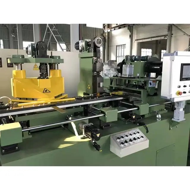
New Silicon Steel Sheet Automatic Cut to Length Line Machine for Transformer Lamination Core with Motor PLCS Industrial Use