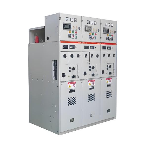
Maintenance of Main and Control Circuits in Low-Voltage Switchgear (Dust Removal); Inspection and Maintenance of Isolators, Circuit Breakers, Contactors, and Relays
I. Preparation and Standards Before Maintenance
Pre-Maintenance Preparations:
(1) Working Conditions: Scheduled shutdown and power disconnection.
(2) Tools and Instruments:Measuring instruments and tools including: insulation resistance tester (megger), clamp meter, multimeter, combination wrenches, voltage tester, electrician pliers, screwdrivers, utility knife, etc.
(3) Personal Protective Equipment (PPE):Safety helmet, insulating mat, insulating shoes, grounding wires, face mask.
(4) Materials and Spare Parts:Conductive grease, sandpaper, clean cloth, wires, blower, replacement components.
(5) Safety and Technical Measures:Complete and issue work permits and power on/off permits; conduct work content briefing; verify implementation of safety measures; review and confirm safety precautions.
Coordination: Shut down equipment and disconnect power. Verify absence of voltage and hang "Under Maintenance" signs. For busbar maintenance, install grounding wires, set up warning signs, and assign a dedicated supervisor during work.
II. Internal Maintenance of Low-Voltage Switchgear
Before starting maintenance, open the cabinet door and use a blower to remove accumulated dust inside the cabinet.
III. Maintenance Standards for Main and Control Circuits
Inspect busbars and main terminal connections for discoloration or looseness. Ensure no deformation or bending, and that electrical clearances meet standards (phase-to-phase >20mm at 380V, phase-to-enclosure >100mm).
Clean cable trenches—ensure no standing water or debris; supports should be intact, secure, and free from corrosion; covers must be complete; rodent-proofing at exits leading outdoors must be effective.
Control circuit wiring must be correct, neat, tight, clearly labeled; fuse connections must show no discoloration or looseness.
Panel indicators must be intact and reliable. Use a multimeter to test selector switches and push buttons—contact resistance should be less than 0.5Ω. Switches and buttons must operate smoothly without sticking.
Inspect primary contacts of drawer-type units for burn marks; spring pressure should be even and contact good. Secondary contacts’ metal spring contacts must not be bent or deformed. Measure contact resistance between secondary plug and socket—must be less than 0.5Ω.
IV. Isolator Switch Maintenance Standards
Operating handle should move smoothly and reliably; linkage base must show no burn or discharge marks; open/closed positions must be fully engaged; set screws, pins, and rods must be intact and secure.
Insertion depth of moving and fixed contacts must be no less than 2/3 of the blade width; contact area must cover at least 75% of the contact clip.
Moving and fixed contact surfaces must be free from burning; contact must be tight. If oxidation is present, clean the oxidized areas and apply a thin layer of Vaseline or conductive grease to prevent further oxidation.
Contact pressure: 45–80N for switches below 200A; 75–100N for 250–400A isolators; 150–220N for 500A and above. Adjust if out of range.
V. Air Circuit Breaker Maintenance Standards
Open the breaker housing and check incoming/outgoing lines for discoloration or looseness. Main contacts must show no burn marks. Operate the breaker twice—moving and fixed contacts must engage tightly with even pressure. Measure resistance with a multimeter—should be less than 0.2Ω. Arc chutes must be intact and undamaged.
After reassembly, the operating handle must move freely without obstruction. Pressing the test button should cause immediate tripping.
VI. AC Contactor Maintenance Standards
The short-circuit ring on the electromagnetic core must be securely fastened. When energized, the contactor should operate silently. The core surface must be clean and free from oil; coil insulation must be undamaged; coil surface must show no discoloration or overheating.
Remove the arc chute and inspect main contacts—they must make tight contact, show no burns, operate smoothly without sticking, and have even pressure. Contact gap must be within acceptable limits.
Components inside the arc chute must be intact; smoke residue must be cleaned. Linkage mechanism must have good insulation, with no deformation, displacement, or loosening.
Auxiliary contacts must operate smoothly without sticking; normally open and normally closed contacts must make good contact with no arcing damage.
VII. Relay Maintenance Standards
Inspect relay appearance—no contact burn marks. Energize the coil at rated voltage—the relay should pull in smoothly without noise or vibration. In the closed position, use a multimeter to confirm all contacts conduct properly.
For thermal relays, verify setting values are appropriate for the connected equipment. Press the test button and use a multimeter to confirm auxiliary contact operation is normal.
Thermal relays must be calibrated and operate sensitively and reliably.
For electromagnetic current relays, error between operating value and scale value must not exceed ±5%.
VIII. Post-Maintenance Measurements and Tests
After maintenance, count tools and ensure no tools or debris remain inside the cabinet. Measure main circuit insulation resistance: using a 500V megger, readings must be ≥5MΩ for 380V circuits, and ≥0.5MΩ for 36V control circuits. Insulation resistance between breakers, busbars, ground, and phases must exceed 10MΩ.
Remove "Under Maintenance" signs, remove grounding wires, close and lock cabinet doors. Set switch to "Test" position, close the breaker to energize, and perform no-load open/close tests. Operate open/close functions twice—switch must operate smoothly and reliably without sticking; indicators must function correctly.
Clean the work area thoroughly. Complete maintenance records—collect documentation, and fully record any replaced parts or adjusted components in the equipment logbook. Conclude maintenance and notify operators to test run the equipment.
For equipment with replaced control components, measure three-phase operating current for balance and verify normal three-phase voltage. Record results. Observe operation for at least 0.5 hours. Only release for service after confirmation and signature by all three parties (contractor, supervisor, and user).