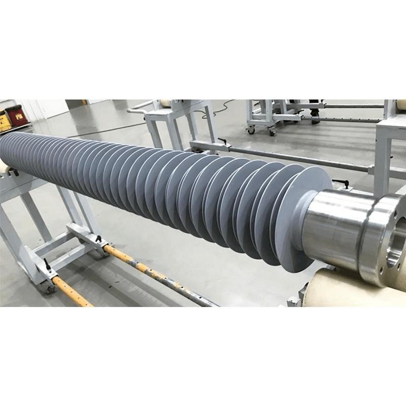
Insulators are typically made of porcelain material and are therefore also known as porcelain insulators. They have a dense structure with a glazed surface to enhance electrical insulation performance. Insulators for different voltage levels have varying effective heights and surface configurations. The higher the voltage level, the longer the insulator and the greater the number of sheds.
1. Functions of Insulators
High-voltage insulators must possess sufficient electrical insulation strength and mechanical strength. They are mainly classified into two types: station insulators and line insulators.
Station insulators are widely used indoors in substations. Station insulators are further divided into post insulators and bushing insulators, each available in indoor and outdoor versions. Outdoor insulators are generally designed with a shed structure. In substations, post insulators support and secure busbars and live conductors in indoor and outdoor switchgear, ensuring adequate insulation distance between the busbars or live conductors and ground. They are also used in electrical equipment to support current-carrying conductors. Bushing insulators (shortened to bushings) are used for busbars passing through walls, fixing conductors in enclosed switchgear, and connecting to external conductors (busbars).
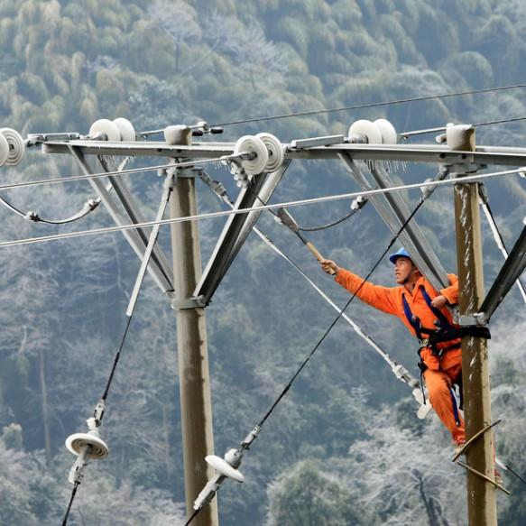
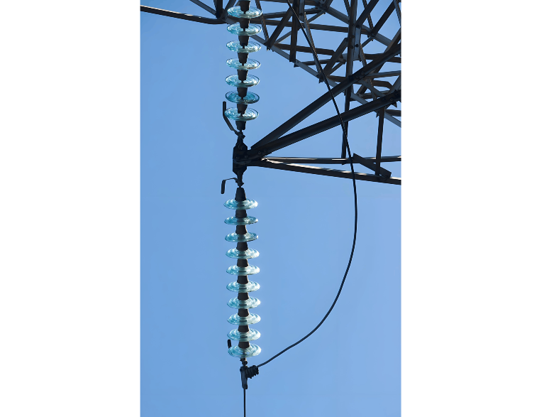
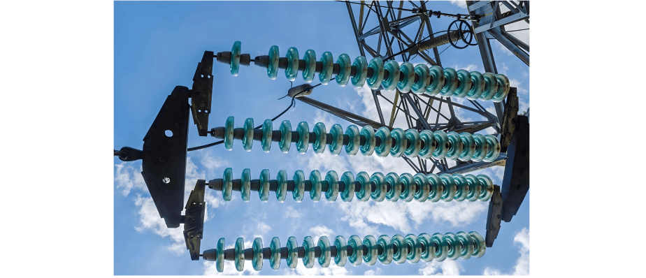
In outdoor installations, line insulators are used for flexible busbars. Line insulators are categorized into suspension insulators and pin insulators.
2. Causes of Insulator Damage
Insulator damage is generally caused by the following factors:
Improper installation leading to mechanical loads exceeding specified values;
Incorrect selection, where the insulator's rated voltage is lower than the operating voltage;
External damage from sudden temperature changes, hail, or other mechanical forces;
Surface contamination, which may cause flashover under rainy, snowy, or foggy conditions;
Excessive electromagnetic and mechanical forces acting on the insulator during short-circuit events in electrical equipment.
3. Causes and Handling of Insulator Flashover Discharge
Causes of insulator flashover discharge include:
Accumulation of dirt on the insulator surface and within shed cavities. Although the insulator may have adequate dielectric strength when dry, its strength decreases when wet, forming a discharge path and increasing leakage current, leading to surface breakdown and discharge;
Even with minimal surface contamination, overvoltage in the power system can cause flashover discharge on the insulator surface.
After a flashover discharge, the insulator's surface insulation performance is significantly reduced and should be replaced immediately. Non-flashed insulators should be inspected and cleaned. More importantly, maintenance and cleaning cycles should be established based on environmental conditions, with regular inspections and cleaning conducted to prevent flashover accidents.
4. Regular Inspection and Maintenance of Insulators
Over long-term operation, the insulation capability and mechanical strength of insulators gradually deteriorate. Busbar joints may also experience increased contact resistance due to thermal cycling. To ensure safe operation, maintenance must be strengthened, and regular inspections carried out. The following practices are generally recommended:
Keep insulators clean and free of contamination. The porcelain parts should be free of cracks or damage, and regular cleaning and inspection should be performed.
Check for flashover marks on the porcelain surface and inspect hardware for rust, damage, or missing split pins.
Check bolted connections between busbars or between busbars and equipment terminals for looseness, overheating, or poor contact.
Inspect busbar expansion joints for cracks, creases, or broken strands.
In dusty or corrosive environments, increase the frequency of insulator cleaning and implement effective anti-pollution measures.