
CIS (Vāyugata Sāndhārak) yāni vāyugata sāndhāraka pūrayanaya eka. Busbar ek ādhāra mārgaya, jaththā multiple devices samānā parallel kara yanvā gannawa. CIS ma busbara antaranga akāsaya relativēva nisala, atha api thunakā vōltajanaya atha current wana karana gannawa. Local discharge, eya vādiya vithara pavattu nisa, inter - phase insulation labha ganna bahu anupatikāva, atha equipment safe atha stable operation kara tikkuna karana bahu anupaththāva. Lihini ek local discharge fault saha CIS busbar analysis atha solution ekena, atha improved fastening scheme saha CIS busbar bolts reference karana eka.
Fault Situation
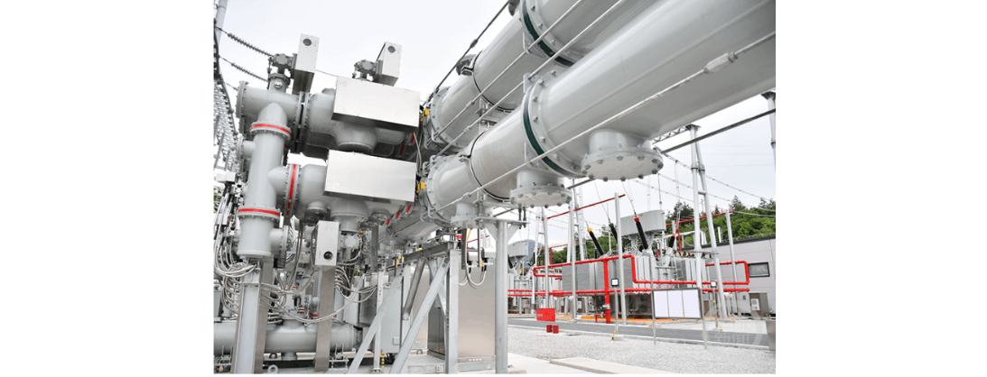
Ek 220 kV CIS ek substation ma December 20, 2016 la put into operation. March 2017 ma, live detection saha substation, operation and maintenance personnel busbar ma very - high - frequency (VHF) signals clear detect karoth, preliminarily determining busbar ma local discharge fault presence.
Partial discharge detector (model PDT - 840MS) use karoth live detection, operation and maintenance personnel No. 4 main transformer 220 kV side 204 circuit breaker atha 225 circuit breaker of the 220 kV Xinguo Line ma busbar built - in sensor VHF signals clear detect karoth. Signals two distinct and symmetrical clusters, large discharge quantity show, maximum amplitude 67 dB reach, abnormal internal discharge sounds on - site hear, preliminarily indicating local discharge presence. Company maintenance center re - measurement conduct arrange, abnormal VHF and ultrasonic signals simultaneously detect.
Ultrasonic detection continuous mode peak value approximately 120 mV, 100 Hz frequency correlation, phase mode maximum value about 70 mV. Analysis after, floating discharge caused by inter - phase insulation inside 2B busbar gas chamber between 204 circuit breaker bay of the 220 kV side of the No. 4 main transformer atha 225 circuit breaker bay of the 220 kV Xinguo Line vibration.
Analysis of the Fault Causes
Load Statistics and Inspection of the Faulty Busbar Bay
220 kV Xinguo Line atha No. 4 main transformer 204 circuit breaker loads statistically analyzed. 220 kV B - section busbar load no significant change, not exceed rated value.
Maintenance personnel, manufacturer's technicians, faulty busbar bay disassembly inspection. This busbar 7 m long, 6 inter - phase insulation supports inside. After disassembling, three loose bolts found: first inter - phase insulation component V - phase, fifth inter - phase insulation component V - phase, sixth inter - phase insulation component W - phase. Among them, first bolt loosest, directly remove, large amount of dust around.
Other inter - phase insulators metal inserts threads no obvious damage, insulator material surface no cracks, scratches, or abnormal depressions. Other parts three - phase conductors other inter - phase insulators other connection points no abnormalities. Other 15 inter - phase insulators conductors connection bolts tightening torques meet specified requirements.
Analysis and Verification
Busbar module components quality and installation. Inspection, busbar duct shell conductor comply with manufacturer's drawings technical quality requirements. Components straightness meet drawings shape tolerance requirements. Insulators metal grading inserts casting solidifying mold. Factory assembly process, special fixture used position three - phase conductors relative spatial positions. However, conductors insulators connection bolts tightening torques some cases not fully meet manufacturer's requirements.
Busbar live operation, three - phase currents symmetrical, each phase conductor same alternating electrodynamic force. Three phases symmetrically distributed space. Busbar conductor hollow conductor, higher bending strength than conductors. Normal installation, three - phase conductors not deviate fixed angular position due to electrodynamic force during operation.
Mechanical Strength Calculation. Manufacturer calculates fasteners connection strength, determines external thread bolt internal thread insulator insert connection length needs greater than current design 16 mm, metal shim thickness needs increased at least 7 mm (currently 4 mm). This can meet mechanical strength requirements single - bolt connection, 10 kN electrodynamic force during busbar short - circuit.
Type Tests. 500 A/3 s thermal stability (short - time withstand current) test, 135 kA dynamic stability (peak withstand current) test, especially temperature - rise test under busbar current 7 h/4000 A, show no obvious mechanical loosening or abnormal connections after tests. This indicates existing design for fastening busbar conductors reliable under type - test conditions.
Cause Determination
On - site inspection theoretical analysis, main cause this fault determined: manufacturer's assembly bolts tightening torques do not meet standards, bolts connection length shims thickness cannot meet operational requirements.
Treatment Scheme
On - site inspections theoretical analyses, new bolt - tightening scheme proposed ensure busbar reliable operation.
Employ double - ended screws connected mating manner internal threads metal inserts annular insulators (shorter thread screw side). Apply Loctite 603 adhesive No. 2 surface external threads screw. Apply three longitudinal strips Loctite 603 adhesive intervals approximately 120° along circumference 24 - mm thread length, ensuring entire 360° surface thread coated adhesive screwing. Bolt fully inserted, use special cleaning paper remove excess adhesive.
Use self - locking/anti - loosening nuts combination effectively prevent bolts loosening. Adopt integrated shim component thickness 8 mm.
Use torque wrench tighten bolts, value 75 N·m, upper end (70±7) N·m range. Ensure torque each bolt standard, implement one person works another checks system.
Tightening completed, use vacuum cleaner, special cleaning paper, alcohol thoroughly clean tightened areas cavity areas conductors.
On - Site Treatment
Double - ended bolts used enhance bolts tightening force, self - locking nuts used prevent bolts loosening due to electrodynamic forces normal operation. Manufacturer carried out bolt modification work this GIS busbar according above - mentioned scheme, results after modification satisfactory.


