Analyze the discharge faults of pillar insulators based on multiple means

Overview of the Situation
During the AC commissioning period of a certain substation, a flashover discharge fault of the post insulator occurred. The specific fault situation is as follows:
When closing the 500 kV AC switchyard switch to charge the busbar, the dual - set busbar differential protection of the busbar operated, and the switch tripped. The fault phase was phase B, and the fault current was 5,760 A. The gas composition analysis of the SF₆ gas in the gas chamber was carried out, and the SO₂ content was 5.3 μL/L (the standard is 2 μL/L).
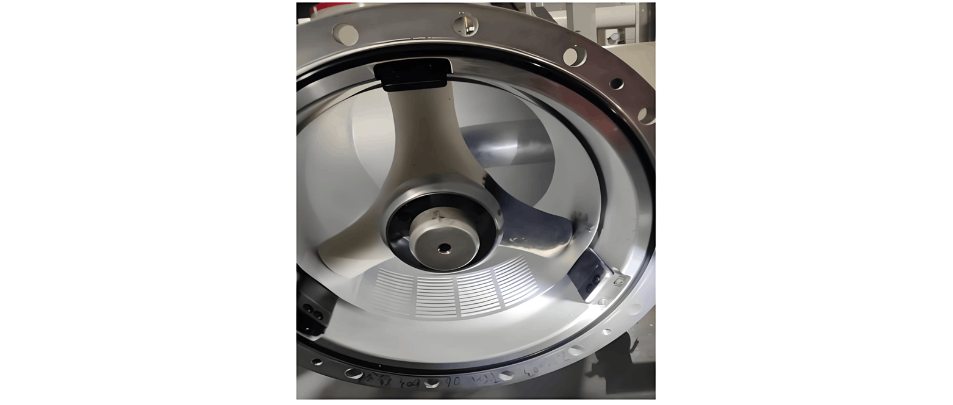
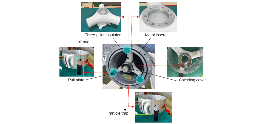
Structure of the Post Insulator
The gas chamber includes three - post insulators, particle traps, pull plates, etc. As shown in Figure 1, during assembly, the three - post insulators and particle traps are first fixed to the metal pull plate with bolts. The shielding cover is installed on the metal insert at the center of the insulator with bolts. The insert is bonded to the insulator by casting. After assembly, it is fixed to the pipe busbar flange through the bolts of the pull plate. The main material of the insulator is epoxy resin, the particle trap is of alloy material, and the limit pad is of insulating material .
The main function of the post insulator is to support the internal conductor and does not serve to isolate the gas chamber. When the equipment is operating normally, the post insulator is evenly stressed under constant gas pressure, as shown in Figure 2. On the other hand, the electric field distribution of the three - post insulator is extremely uneven. The electric field strength at the interface between the metal insert and the epoxy resin is relatively high. This uneven distribution will lead to relatively serious local charge accumulation on the three - post insulator. In case of foreign objects or other situations during operation, flashover discharge may occur.
Re - measurement of Appearance Dimensions
The faulty post insulator was returned to the factory for re - measurement of dimensions and appearance inspection. The faulty busbar post insulators were slightly wiped and the marks were polished. The surface of the post insulator was intact, and no visible cracks, bubbles, or other anomalies were found.
With reference to the drawings, multiple key dimensions of the post insulator, particle traps, shielding covers, pull plates, etc. were re - measured. This involved re - measuring multiple dimensions such as the center - to - center distance of the three legs of the post insulator, circumferential diameter, and angle. All dimensions were found to be qualified.
Dye Penetrant Inspection
Dye penetrant inspection was carried out on the post insulator. After cleaning and grinding, the inspection was conducted. The cleaning agent was sprayed onto the paper, and then the penetrant on the surface of the insulator was wiped clean. After careful inspection, no penetrant seepage was detected, and no anomalies were found in the dye penetrant inspection.
X - ray and Industrial CT Inspection
X - ray inspection was performed on the post insulator. The post insulator was rotated 360° for inspection, and no defects such as poor bonding, bubbles, or cracks were found.
Industrial CT inspection tests were carried out on the post insulator. The internal insulation material was generally uniform, with no air holes, cracks, impurities, or other defects found. There was no poor bonding between the low - voltage end insert and the epoxy resin, nor between the central cylinder and the epoxy resin.
Mechanical Performance Test
Mechanical performance tests were carried out on the post insulator, including a pressure test (12 kN, holding pressure for 30 min) and a torsion test (15 kN, holding pressure for 30 min). The surface of the post insulator was observed for any anomalies, cracks, or damage. No anomalies were found through the mechanical performance test.
Insulation Performance Test
The post insulators were assembled into a busbar test state with new particle traps and the old particle traps (after grinding) returned from the site respectively, and filled with 0.5 MPa SF₆ gas inside.
First, the assessment was carried out according to the in - factory withstand voltage test method: power - frequency withstand voltage (740 kV for 1 min - 381 kV for 5 min), and lightning impulse (±1675 kV, 3 times each); then, the assessment was carried out according to the on - site withstand voltage test method: power - frequency withstand voltage (318 kV for 5 min - 550 kV for 3 min - 740 kV for 1 min - 381 kV for 45 min). All test results were normal, with no discharge or abnormal conditions.
Fault Reproduction Test
Based on the above analysis of the post insulator, it was determined that no fault problems were found in the design and manufacturing stages of the post insulator. It was preliminarily judged that foreign objects on the surface of the post insulator during the installation stage might have caused the flashover discharge. To further confirm the cause of the accident as analyzed, considering the possible hiding places of foreign objects and the situation of non - application of lubricating grease, reproduction tests under various working conditions were carried out, including: applying 1/3 lubricating grease on the post insulator (no discharge), applying 1/2 lubricating grease on the post insulator (no discharge), applying 2/3 lubricating grease on the post insulator (no discharge), applying 1/3 lubricating grease on the post insulator and blowing dust (dust onto the post insulator, no discharge), etc.
Based on the reproduction test results under the above - mentioned working conditions, it can be concluded that single - source lubricating grease contamination or metallic foreign objects are not likely to cause surface flashover breakdown of the insulator; for insulators that break down under power - frequency voltage, both the central insert and the ground - potential insert have obvious ablation marks; for insulators that break down under lightning impulse voltage, the central insert has ablation marks, which is similar to the phenomenon of the on - site fault.


