• Product
  • Suppliers
  • Manufacturers
  • Solutions
  • Free tools
  • Knowledges
  • Experts
  • Communities
Search


Comprehensive Guide to High-Frequency Fault Handling of AC Contactors: 90% of Problems Solved with One Method

Felix Spark
Felix Spark
Field: Failure and maintenance
China

1. Fault Phenomena, Cause Analysis and Handling Methods

Contactor does not operate or operates abnormally after coil energization

  • Open circuit in coil control circuit; Check if there is wire breakage or loosening at the terminal blocks. If there is a wire breakage, replace the corresponding wire; if there is loosening, fasten the corresponding terminal block.

  • Coil damage; Measure the coil resistance with a multimeter. If the resistance is ∞, replace the coil.

  • Thermal relay not reset after operation; Use the resistance range of a multimeter to measure the resistance between the two normally closed contacts of the thermal relay. If the resistance is ∞, press the reset button of the thermal relay.

  • Rated voltage of the coil is higher than the line voltage; Replace with a coil suitable for the control circuit voltage.

  • Excessive pressure of contact spring or release spring; Adjust the spring pressure or replace the spring.

  • Poor contact of button contacts or auxiliary contacts; Clean the contacts of the button or replace the corresponding component.

  • Excessive contact overtravel; Adjust the contact overtravel.

Contactor does not release or releases with delay after coil de-energization

  • No air gap in the middle column of the magnetic system, resulting in excessive residual magnetism; File off a part of the pole surface at the residual magnetism gap to make the gap 0.1~0.3mm, or connect a 0.1μF capacitor in parallel at both ends of the coil.

  • Oil on the surface of the iron core of a new contactor or oil accumulation after a period of use; Wipe off the anti-rust oil on the iron core surface. The iron core surface should be flat but not too smooth, otherwise it may easily cause delayed release.

  • Poor anti-welding performance of contacts; When starting the motor or in case of line short circuit, large current causes the contacts to weld and fail to release (pure silver contacts are more prone to welding). The main contacts of AC contactors should use silver-based alloys with strong anti-welding ability, such as silver-iron, silver-nickel, etc.

  • Incorrect wiring of the control circuit; Correct the incorrectly wired parts according to the control circuit diagram.

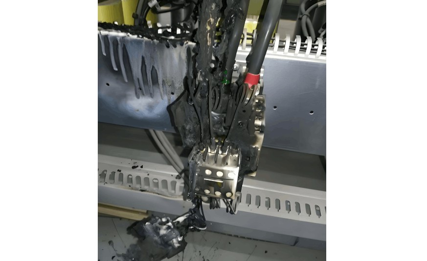
Coil overheating, burning or damage

  • The operating frequency and duty cycle of the coil exceed the product technical requirements; Replace with a coil that matches the corresponding operating frequency and duty cycle.

  • Uneven pole surface of the iron core or excessive air gap in the middle column; Clean the pole surface, adjust the iron core, or replace the coil.

  • Mechanical damage, stuck moving parts; Repair the mechanical parts and replace the coil.

  • Excessively high ambient temperature, humid air or corrosive gas causing coil insulation damage; Change the installation location and replace the coil.

  • Excessive noise from the electromagnet

  • Broken short-circuit ring; Replace the short-circuit ring or the iron core.

  • Excessive contact spring pressure or excessive contact overtravel; Adjust the contact spring pressure or reduce the overtravel.

  • Loose connecting pin between the armature and the mechanical part, or loose clamping screws; Reinstall the connecting pin and fasten the clamping screws.

Coil overheating, burning or damage.jpg

Phase-to-phase short circuit

  • Excessive dust accumulation on the contactor or moisture/oil contamination causing insulation damage; Regularly clean the contactor to keep it clean and dry.

  • In circuits using only electrical interlocking, the switching time of reversible contactors is shorter than the arc duration; Add mechanical interlocking.

  • Broken arc-extinguishing cover, or contactor components carbonized due to arc burning; Replace the arc-extinguishing cover or the damaged components.

Handling Methods for Excessive Noise Fault of AC Contactors

For an AC contactor with excessive noise during operation, the following measures can be taken:

  • Insufficient power supply voltage leading to insufficient electromagnetic attraction and noise; Take measures to increase the voltage of the control circuit.

  • Improper assembly of the magnetic system, skewing due to vibration, or stuck mechanical parts, preventing the iron core from being fully attracted; Adjust the magnetic system and identify and eliminate the causes of inflexible mechanical parts.

  • Rust on the pole surface or foreign objects (such as oil, dust, lint, etc.) on the iron core pole surface; Clean the iron core pole surface.

  • Excessive contact spring pressure causing electromagnet noise; Usually, adjust the contact spring pressure.

  • Noise caused by a broken short-circuit ring; Replace the iron core or the short-circuit ring.

  • Excessive wear and unevenness of the iron core pole surface; Replace the iron core.

  • Inter-turn short circuit of the coil; Usually, replace the coil.

Give a tip and encourage the author!
Recommended
10kV RMU Common Faults & Solutions Guide
Application Issues and Handling Measures for 10kV Ring Main Units (RMUs)The 10kV ring main unit (RMU) is a common electrical distribution device in urban power distribution networks, primarily used for medium-voltage power supply and distribution. During actual operation, various issues may arise. Below are common problems and corresponding corrective measures.I. Electrical Faults Internal Short Circuit or Poor WiringA short circuit or loose connection inside the RMU can lead to abnormal operati
Echo
10/20/2025
High-Voltage Circuit Breaker Types & Fault Guide
High-Voltage Circuit Breakers: Classification and Fault DiagnosisHigh-voltage circuit breakers are critical protective devices in power systems. They rapidly interrupt current when a fault occurs, preventing damage to equipment from overloads or short circuits. However, due to long-term operation and other factors, circuit breakers may develop faults that require timely diagnosis and troubleshooting.I. Classification of High-Voltage Circuit Breakers1. By Installation Location: Indoor-type: Insta
Felix Spark
10/20/2025
10 Prohibitions for Transformer Installation and Operation!
10 Prohibitions for Transformer Installation and Operation! Never install the transformer too far away—avoid placing it in remote mountains or wilderness. Excessive distance not only wastes cables and increases line losses, but also makes management and maintenance difficult. Never choose transformer capacity arbitrarily. Selecting the right capacity is essential. If the capacity is too small, the transformer may be overloaded and easily damaged—overloading beyond 30% should not exceed two hours
James
10/20/2025
How to Maintain Dry-Type Transformers Safely?
Maintenance Procedures for Dry-Type Transformers Put the standby transformer into operation, open the low-voltage side circuit breaker of the transformer to be maintained, remove the control power fuse, and hang a "DO NOT CLOSE" sign on the switch handle. Open the high-voltage side circuit breaker of the transformer under maintenance, close the grounding switch, fully discharge the transformer, lock the high-voltage cabinet, and hang a "DO NOT CLOSE" sign on the switch handle. For dry-type trans
Felix Spark
10/20/2025
Send inquiry
Download
Get the IEE Business Application
Use the IEE-Business app to find equipment, obtain solutions, connect with experts, and participate in industry collaboration anytime, anywhere—fully supporting the development of your power projects and business.