| Brand | Switchgear parts |
| Model NO. | High frequency online UPs power supply (Single phase/220V) |
| Rated frequency | 50/60Hz |
| Output Voltage | 200-240VAC |
| Capacity | 3kVA |
| Series | HBG |
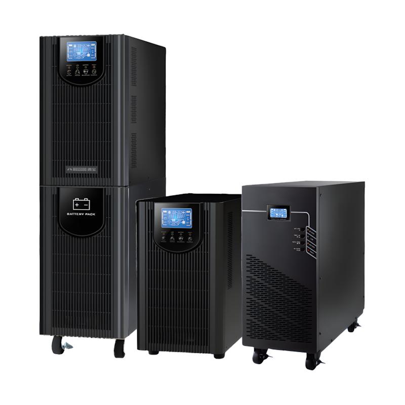
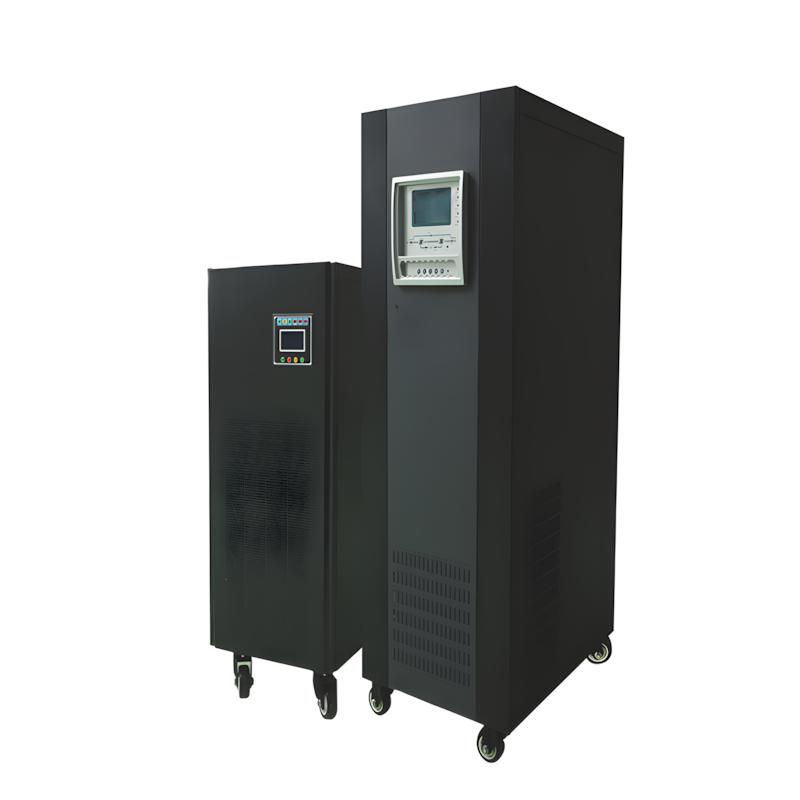
The HBG series fully embodies the essence of cuting-edge technology. The whole machine adopts the world's mostadvanced DSP digital control technology and ultra-high frequency control technology to create a small size, light weight and highwork eficiency; zero conversion design and pure sine wave The output technology ensures that the user device is suitable for avariety of devices. A unigue AC-DC conversion circuit is used to detect the output current and output voltage of the commercialpower supply, and through the high-frequency pulse width modulator, the current waveform of the input power supply is consistenwith the voltage waveform phase, so as to achieve a high input power factor areater than 95%.. Under normal conditions of themains, the mains obtains the DcBuS DC voltage through the Ac-Dc circuit, and then converts the DcBuS to 220V AC outputthrough the inverter. wave power. The excellent lGBT is used as the power conversion element. Due to the high-freguencyswitching characteristics of the lBGT, the operating frequency of the UPS inverter can reach 40KHz. The working eficiency of theinverter is improved, and the eficiency of the UPS is also improved. The noise of the inverter is reduced, so that the HBG seriesUPS can be placed directly in the computer room without affecting your work. online high-freguency HBG series UPsthrough the RS232 flood interface with power monitoring software, connect the UPs with the network server. providebower status at any time: and realize timind self-check, automaic storage, automatic timina switch machine and record poweStatus and other inteligent functions to achieve zero distance beween man-machine communication, When the utility power isinterrupted, the UPS will notify the server to prepare for shutdown, automatically save all data to disk, and execute the normashutdown command. Even in an unmanned network environment, the data security of the network system can be guaranteed
Features
True online double conversion
Input power factor correction
Output power factor up to 0.8
Ultra-wide mains input range(110V-300V)
Efficient frequency conversion mode OEcO mode provides energy saving effect (only for 1-3K models)
Compatible generator input
Long-term model charging current up to 6A
Optional sophisticated SNMP card can be used alone or with USB
Perfect monitoring with RS232
Simple operation control through display
And comprehensive display monitoring UPS status
Application field
Widely used in important data fields such as network management centers and computer centers, banking and securities, taxation, communication, postal services, broadcasting and television, public security, transportation, electricity, healthcare, industrial control, and national defense.
Technical Parameter
|
Model Specification |
HBG-1kH(S) |
HBG-2kH(S) |
HBG-3kH(S) |
HBG-6kH(S) |
HBG-10kH(S) |
|
Phase |
Single Phase Input and Output |
|
|
|
|
|
Capacity |
1000 VA / 800 W |
2000 VA / 1600 W |
3000 VA / 2400 W |
6000 VA / 4800 W |
10000 VA / 8000 W |
|
Input |
|||||
|
Voltage Range |
110 - 300VAC at 50% load; 160 - 300 VAC at 100% load |
110 - 300VAC at 50% load; 176 - 300 VAC at 100% load |
|||
|
Frequency Range |
40Hz ~ 70 Hz |
46Hz ~ 54 Hz or 56Hz ~ 64 Hz |
|
||
|
Power Factor |
≥ 0.99 at 100% load |
||||
|
Output |
|||||
|
Output Voltage |
200/208/220/230/240VAC |
208/220/230/240VAC |
|||
|
Voltage Range (Battery Mode) |
± 1% |
||||
|
Frequency Range (Synchronous Correction Range) |
47 ~ 53 Hz or 57 ~ 63 Hz |
46Hz ~ 54 Hz or 56Hz ~ 64 Hz |
|||
|
Frequency Range (Battery Mode) |
50 Hz ± 0.25 Hz or 60Hz ± 0.3 Hz |
50 Hz ± 0.1 Hz or 60 Hz ± 0.1 Hz |
|||
|
Crest Factor |
3:1 |
||||
|
Ripple Distortion |
≤ 3% THD (Linear Load); ≤6% THD (Non-linear Load) |
≤ 3% THD (Linear Load); ≤5% THD (Non-linear Load) |
|||
|
Harmonic Distortion |
0 |
||||
|
Conversion Time |
|
|
|
|
|
|
AC to DC |
4 ms (Standard Conditions) |
0 |
|
||
|
Inverter to Bypass |
|
|
|
|
|
|
Waveform (Battery Mode) |
Pure Sine Wave |
|
|
|
|
|
Efficiency |
|||||
|
Mains Mode |
88% |
89% |
90% |
92% |
93% |
|
Battery Mode |
83% |
87% |
89% |
89% |
91% |
|
Battery |
|
|
|
|
|
|
Standard Unit |
|
|
|
|
|
|
Battery Model |
12V / 7AH |
||||
|
Quantity (Cells) |
2 |
4 |
6 |
12 |
16 |
|
Maximum Charging Current |
1.0A (Max) |
Preset:1.0 A, Max:2.0A |
|||
|
Charging Voltage |
27.3VDC ± 1% |
54.7VDC ± 1% |
82.1VDC ± 1% |
163.8VDC ± 1% |
218.4VDC ± 1% |
|
Long-term Unit |
Depends on Power Supply Time |
||||
|
Battery Model |
|
6 |
6 |
16 |
16 |
|
Quantity (Cells) |
3 |
6 |
8 |
16 |
16 |
|
Maximum Charging Current |
1.0A/2.0A/4.0A/6.0 A |
Preset:4.0 A ± 10%, Max:6.0A ± 10% |
|||
|
Charging Voltage |
41.0VDC ± 1% |
82.1VDC ± 1% |
109.4VDC ± 1% |
218.4VDC ± 1% |
218.4VDC ± 1% |
|
Appearance |
|
|
|
|
|
|
LCD or LED Display |
Load Size, Battery Capacity, Mains Mode, Battery Mode, Bypass Mode, Fault Indication |
||||
|
Alarm |
|
|
|
|
|
|
Battery Mode |
Beeps every 4 seconds |
||||
|
Low Battery |
Beeps every 1 second |
||||
|
Overload |
Beeps every 0.5 second |
||||
|
Error |
Continuous Beep |
||||
|
External Dimensions |
|
|
|
|
|
|
Standard Unit |
|
|
|
|
|
|
Dimensions (W×D×H)mm |
145 X 282 X 220 |
145 X 397 X 220 |
190 X 421 X 318 |
190 x 369 x 688 |
190 x 442 x 688 |
|
Net Weight (kgs) |
9.8 |
17 |
27.6 |
43 |
63 |
|
Long-term Unit |
|||||
|
Dimensions (W×D×H)mm |
145 X282 X 220 |
145 X397 X 220 |
|
190 x369 x 318 |
190 x442 x 318 |
|
Net Weight (kgs) |
4.1 |
6.8 |
7.4 |
12 |
16 |
|
Operating Environment |
|
|
|
|
|
|
Temperature and Humidity |
Relative Humidity 20-90% and Temperature 0-40°C (No Condensation) |
Relative Humidity 0-95% and Temperature 0-40°C (No Condensation) |
|||
|
Noise |
Less than 50dB@ 1m |
Less than 55dB @ 1m |
|||
|
Control Management |
|||||
|
Smart RS-232 / USB |
Supports Windows® 2000/2003/XP/Vista/2008, Windows® 7/8, Linux, Unix, and MAC |
||||
|
Optional SNMP |
Power Management Supports SNMP Management and Network Management |
||||
When the UPS is set to constant voltage and frequency mode, the output power will be derated by 40%. When the UPS output voltage is set to 208VAC, the output power will be derated by 10%. "S" represents the long-life model. When the internal battery count is changed to 16-19 units, the machine will derate the output according to the following formula: P=Prating × (N/20 × 100%). If the machine is installed at an altitude exceeding 1,000 meters, the output power will be derated by 1% for every 100-meter increase in elevation. Any changes to current product specifications will not be separately notified
Follow these safety guidelines to avoid accidents and equipment damage: ① Electric shock prevention: Do not touch the internal components of the UPS when it is powered on; keep the UPS away from children to prevent accidental contact with sockets; ② Fire prevention: Do not place flammable materials (e.g., paper, cloth) around the UPS; do not block the heat dissipation vents to avoid overheating and fire; ③ Battery safety: Do not short-circuit the battery terminals; do not disassemble or incinerate the battery (risk of explosion); dispose of old batteries according to local environmental regulations (do not discard in household waste); ④ Emergency handling: In case of smoke, odor or abnormal noise from the UPS, immediately unplug it from the mains and disconnect the battery; contact after-sales service for repair (do not attempt to repair it yourself); ⑤ Transportation safety: When moving the UPS, avoid dropping or shaking it violently; for models with built-in batteries, follow air/land transportation regulations for lithium/lead-acid batteries.
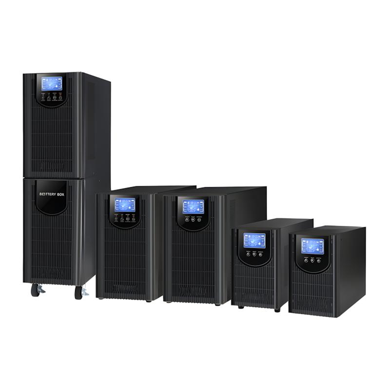
It is a compact uninterruptible power supply designed for single-phase grid and single-phase load scenarios, mainly used to protect office computers, monitoring systems, home electronics and small servers. Core functions: ① Provide seamless power supply during grid outages (switching time <2ms) to prevent data loss or equipment shutdown; ② Stabilize voltage, filter harmonics and suppress surges to isolate grid anomalies (e.g., voltage spikes, brownouts); ③ Ensure pure sine wave output for sensitive equipment. Working principle: Adopt high-frequency double-conversion technology (20kHz–50kHz)—single-phase AC input is rectified into DC power, then inverted into stable single-phase AC output. When mains power fails, the built-in/external battery instantly supplies DC power to the inverter, realizing zero-interruption power supply. Its high-frequency design makes it smaller, lighter and more energy-efficient than traditional low-frequency UPS.