| Brand | Switchgear parts |
| Model NO. | Modular UPS emergency power supply |
| Rated frequency | 50/60Hz |
| Output Voltage | 380/400/415VAC |
| Input Voltage | 380/400/415VAC |
| Capacity | 300kVA |
| Series | HBM |
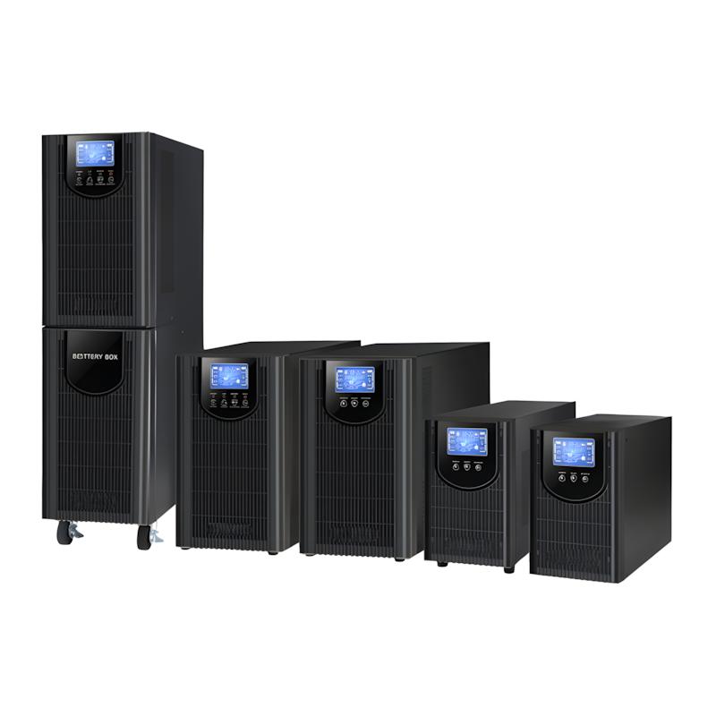
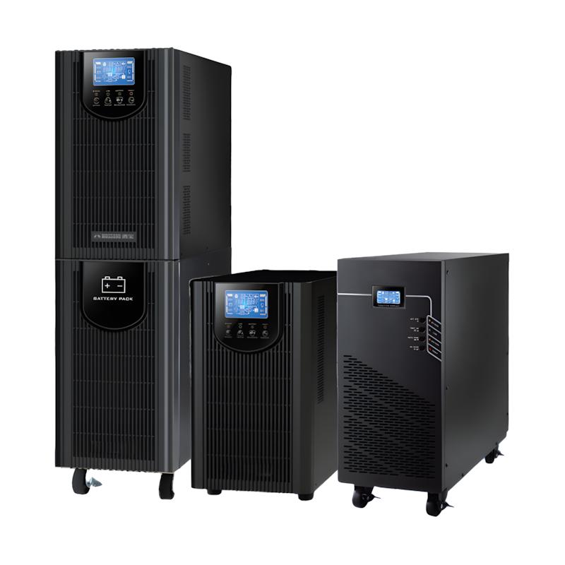
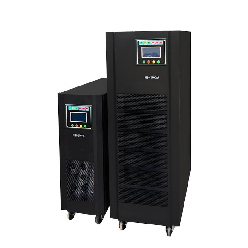
Product application: This product has a wide range of applications and provides safe, stable, reliable, and environmentally friendly power protection for critical loads such as data centers, financial centers, government and enterprise data centers, medical education, etc.
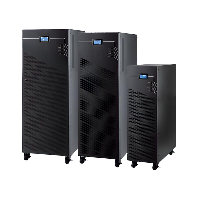
HBM50-600KW is a new generation of three in three out modular UPS launched by our company. The product adopts digital control, modular design, and N+X parallel redundancy technology, which integrates the most advanced technological achievements in the fields of power electronics and automatic control. It is a benchmark product in the field of modular UPS.
The product capacity covers various power ranges between 50kW and 600kW, making it convenient for users to flexibly configure and gradually invest. It can run 4 parallel machines up to 2400kW.
Product features
Technical Specifications
All parts of the architecture are digitally controlled, with excellent performance and high system stability. It has self-protection and fault diagnosis capabilities, while also avoiding the risk of analog device failure, making the control system more stable and reliable.
Adopting advanced three-level technology, the overall efficiency of the machine is as high as 96%.
High power density design, 50KW single module size (W × D × H) 440 × 620 × 130mm.
The output can be connected to a completely unbalanced load. When the output is connected to an unbalanced load, the input current is balanced in three phases, which can balance the load of the three-phase power grid.
high reliability
The N+X parallel redundancy design ensures a system availability of 99.999% and an MTBF of over 250000 hours, meeting the high reliability requirements of critical loads on the power supply system; The flexible parallel redundancy setting allows the system to provide maximum output capacity.
Control system parallel redundancy, with control methods of decentralized control and centralized management; The centralized control unit is redundantly connected in parallel, and the failure of one of them does not affect the overall operation of the machine; The optimized distributed combiner cabinet ensures the safety of system parallel connection.
The centralized monitoring module has hot swappable function. When the monitoring module is unplugged, the system can work normally using centralized bypass power supply, which improves the power supply capacity of the bypass power supply.
EPO function, press the EPO button in emergency situations to shut down urgently; The EPO button is designed for protection and has a remote emergency shutdown (REPO) function to prevent accidental operation.
Convenient and flexible
Modular design, consisting of 1 to 12 modules connected in parallel, with a maximum power of 600kW. Users can gradually increase the number of modules with flexibility; Using hot swappable technology, modules can be added and removed online, achieving "zero" maintenance time.
The downtime for maintenance is short. The number of faulty modules is less than or equal to the number of redundant modules, and the downtime for maintenance is zero; The number of faulty modules is greater than the number of redundant UPS modules, and the downtime for maintenance shall not exceed 5 minutes.
The cabinet LCD touch color screen display provides rich UPS status information, warning information, fault information, etc; Single module LED display, users can understand the working status of the module through the module LED lights.
In case of emergency, UPS can switch to the maintenance bypass power supply, and maintenance personnel can safely perform online repairs.
intelligent design
The charging current can be set, and the user configured battery capacity and charging current can be set through the panel LCD to achieve automatic smooth switching between constant voltage charging mode, constant current charging mode, and float charging mode.
Intelligent charging method, adopting advanced two-stage three-stage charging method, can effectively balance the goals of fast charging and extending battery life, saving users' battery investment.
Provide a wide range of optional accessories, including isolation transformers, distribution panels, SNMP cards, relay dry connection cards, etc., to form a small to medium-sized distribution system.
Green Design
Adopting a 19 inch standard cabinet, it perfectly matches the application environment of the computer room and saves the usable area of the computer room.
Parallel sharing of batteries greatly reduces the number of battery configurations, allowing users to fully configure batteries based on backup time.
The number of external batteries is optional, and users can choose 30/32/34/36/38/40/42/44/46/48/50 cells (30-50 cells are optional) according to their needs.
Technical Specifications
|
Model |
HBM90-30 |
HBM150-30 |
HBM300-30 |
|
Capacity |
|
|
|
|
UPS Cabinet |
30-90kVA |
30-150KVA |
30-300KVA |
|
Power Module |
30kVA |
30kVA |
30kVA |
|
Input |
|
|
|
|
Input Mode |
Three-phase Four-wire + Ground |
||
|
Rated Voltage |
380/400V/415Vac |
||
|
Voltage Range |
208~478Vac |
||
|
Frequency Range |
40~70Hz |
||
|
Power Factor |
≥0.99 |
||
|
Bypass Range |
380 upper limit: 25% (optional +10%, +15%, +20%)
400 upper limit: 20% (optional +10%, +15%)
415 upper limit: 15% (optional +10%)
Lower limit: -45% (optional -20%, -30%)
Bypass frequency protection range: ±10% |
||
|
Input Current Harmonic |
≤3% (100% Non-linear Load) |
||
|
Output |
|
||
|
Output Mode |
Three-phase Four-wire + Ground |
||
|
Rated Voltage |
380/400V/415Vac |
||
|
Power Factor |
0.9 or 1 |
||
|
Voltage Accuracy |
±1% |
||
|
Output Frequency |
|
||
|
Mains Mode |
Synchronous with input; when mains frequency exceeds maximum ±10% (can be set to ±1%, ±2%, ±4%, ±5%), output frequency is 50×(±0.2%)Hz |
||
|
Battery Mode |
(50/60±0.2%)Hz |
||
|
Load Crest Factor |
3:1 |
||
|
Switching Time |
Mains mode to bypass mode: 0ms (tracking); Mains mode to battery mode: 0ms |
||
|
Overload Capacity |
Load ≤110%, 60min; ≤125%, maintain 10min; ≤150% maintain 1min; ≥150% switch to bypass immediately |
||
|
Output Voltage Harmonic |
≤2% (100% Linear Load) |
||
|
Efficiency |
95% in Normal Mode |
||
|
Communication Interface |
RS232, RS485, 2 Intelligent Slot (Smart Card Slot), Dry Contact |
||
|
Battery |
|
||
|
Battery Voltage |
±192V±204V±216V±228V±240V DC; (32, 34, 36, 38, 40 cells optional) |
||
|
Charging Current |
|
||
|
UPS Cabinet |
30A Max. |
50A Max. |
100A Max. |
|
Power Module |
10A Max. |
10A Max. |
10A Max. |
|
Working Environment |
|
|
|
|
Working Temperature |
0℃ ~ 40℃ |
0℃ ~ 40℃ |
0℃ ~ 40℃ |
|
Relative Humidity |
0 ~ 95% non condensing |
||
|
Storage Temperature |
-25℃ ~ 55℃ |
||
|
Altitude |
< 1500m |
< 1500m |
< 1500m |
|
Physical Characteristics |
|
||
|
Appearance Dimensions (D×W×H) mm |
|
|
|
|
Cabinet |
840 x 600 x 1400 |
840 x 600 x 1400 |
1100 x 600 x 2000 |
|
Module |
580 x 443 x131 |
580 x 443 x131 |
580 x 443 x131 |
|
Weight (Net Weight) Kg |
|
|
|
|
Cabinet |
158 |
170 |
305 |
|
Module |
30K module, 33.5KGS |
||
|
Execution Standard |
CE,EN/IEC 62040-2, EN/IEC 62040-1-1, YD/T1095-2008 |
||
|
Model |
HBM300-50 |
HBM400-50 |
HBM500-50 |
HBM600-50 |
|
Capacity |
|
|
|
|
|
Cabinet |
50-300KW |
50-400KW |
50-500KW |
50-600KW |
|
Module |
50KW |
50KW |
50KW |
50KW |
|
Maximum Number of Modules |
6 |
8 |
10 |
12 |
|
Input |
|
|||
|
Main Path Input |
|
|||
|
Rated Input Voltage (Vac) |
380/400/415 |
|||
|
Input Voltage Range (Vac) |
138 ~ 485Vac |
|||
|
Wiring Mode |
Three-phase Five-wire |
|||
|
Input Frequency Range (Hz) |
40-70 |
|||
|
Input Power Factor |
≥0.99 |
|||
|
Input Current Harmonic (THDi) |
≤3% (100% Linear Load) |
|||
|
Bypass Input |
|
|||
|
Rated Input Voltage (Vac) |
380/400/415 |
|||
|
Input Voltage Range (Vac) |
220 upper limit: 25% (optional +10%, +15%, +20%) 230 upper limit: 20% (optional +10%, +15%) 240 upper limit: 15% (optional +10%) lower limit: -45% (optional -10%, -20%, -30%) |
|||
|
Wiring Mode |
Three-phase Five-wire |
|||
|
Bypass Synchronous Tracking Range (Hz) |
±10% |
|||
|
Generator Input |
Supported |
|||
|
Power Walking In |
Supported |
|||
|
Bypass Reverse Feeding |
Supported |
|||
|
Output |
|
|||
|
Voltage (Vac) |
380/400/415±1% |
|||
|
Power Factor |
1 |
|||
|
Frequency (Hz) |
|
|||
|
Mains Mode |
±1%/±2%/±4%/±5%/±10% (Configurable) |
|||
|
Battery Mode |
(50/60±0.1%)Hz |
|||
|
Waveform |
Sine Wave |
|||
|
Current Crest Ratio |
3:1 |
|||
|
Output Voltage Harmonic (THDV) |
≤2% (100% Linear Load); ≤3% (100% Non-linear Load) |
|||
|
Switching Time (ms) |
0 |
|||
|
Overall Efficiency (%) |
96 |
|||
|
Overload Capacity |
110% load, transfer to bypass after 60min; 125% load, transfer to bypass after 10min; 150% load, transfer to bypass after 1min |
|||
|
Battery |
|
|||
|
Maximum Module Charging Current (A) |
20 |
|||
|
Battery Voltage |
30~50 cells optional, default 36 cells; optional voltages: ±180V/±192V/±204V/±216V/±228V/±240V/±252/±264/±276/±288/±300Vdc (30/32/34/36/38/40/42/44/46/48/50 cells) |
|||
|
Environment |
|
|||
|
Working Temperature |
0℃ ~ 40℃ |
|||
|
Storage Temperature |
—25℃ ~ 55℃ |
|||
|
Humidity Range |
0 ~ 95% (Non-condensing) |
|||
|
Working Altitude |
< 1500m (Derate for use above 1500m) |
|||
|
Noise (1m Distance) |
<68dB |
<70dB |
<70dB |
<70dB |
|
Other Functions |
|
|
|
|
|
Protection Functions |
Short circuit, overload, over temperature, output over voltage, battery under voltage, fan fault alarm, bypass reverse feeding, lightning protection |
|||
|
Alarm Functions |
Mains abnormality, overload, UPS fault, battery under voltage and other multiple alarm functions |
|||
|
Communication Functions |
CAN, RS485, Network Interface, Dry Contact, Parallel Interface, LBS Interface, Smart Card Slot, Temperature Sensor Interface |
|||
|
Mechanical Characteristics |
|
|||
|
Dimensions (W×D×H) |
|
|||
|
Cabinet (mm) |
600×850×2000 |
600×850×2000 (Standard); 1200×850×2000 (Fully Loaded) |
1200×850×2000 |
1200×850×2000 |
|
Module (mm) |
440×620×130 |
|||
|
Net Weight |
|
|||
|
Cabinet (kg) |
260 |
280/600 |
645 |
720 |
|
Module (kg) |
32 |
|||
|
Execution Standard |
YD/T 2165-2010 |
|||
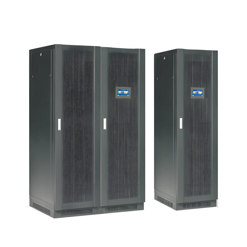
Compared with traditional tower UPS, it has obvious advantages: ① Flexible expansion: Capacity can be increased by adding modules on demand, avoiding initial over-investment; ② High reliability: N+X redundancy design eliminates single-point failure, and hot-swappable modules reduce MTTR (mean time to repair) to minutes; ③ Energy saving: AC-AC efficiency up to 97%, ECO mode efficiency up to 99%; ④ Space-saving: High power density design (e.g., 60kW module in 3U space) saves installation space; ⑤ Easy maintenance: Independent module design simplifies fault diagnosis and replacement.
Its core function is to provide high-reliability uninterrupted power supply for critical loads, with flexible capacity expansion and low-maintenance advantages. The working principle is based on N+X redundant parallel technology: each power module works independently and shares the load evenly; when the mains is normal, it stabilizes voltage, filters harmonics and supplies power to loads while charging batteries; when the mains fails, it switches to battery power supply with 0ms conversion time. Failed modules can be hot-swapped without shutting down the system, ensuring 99.999% system availability.