| Brand | Switchgear parts |
| Model NO. | High frequency on-line (rack type) UPS power supply |
| Output Voltage | 110-127VAC |
| Input Voltage | 110-127VAC |
| Capacity | 6kVA |
| Series | HBG |
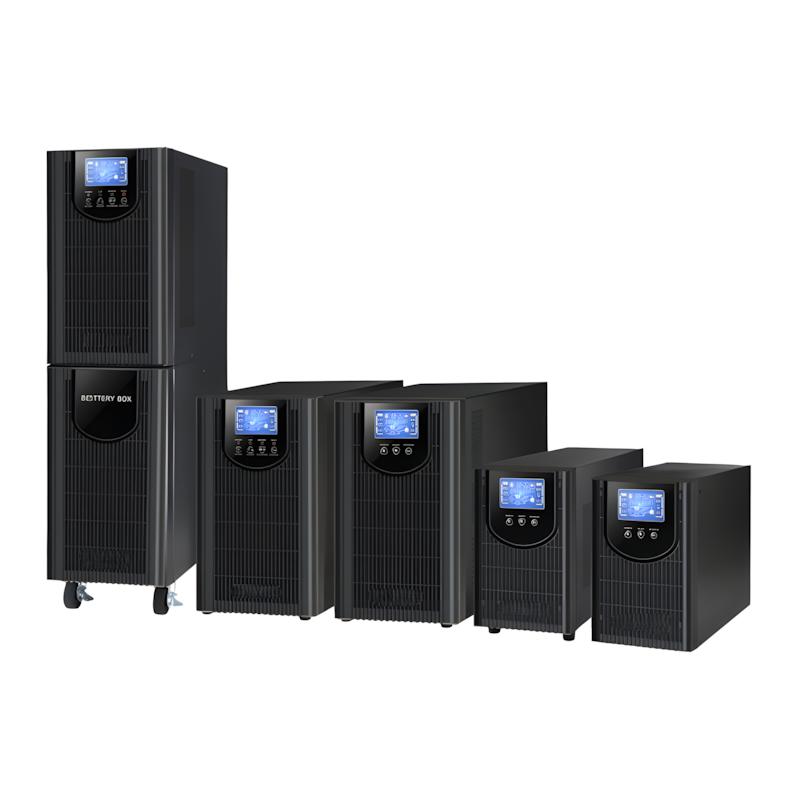
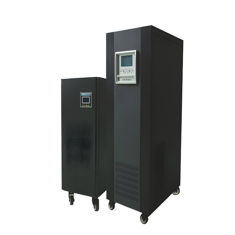
HBG series fully condenses the essence of cutting-edge technology. The whole machine adopts the world's advanced DSP digital control technology and ultra-high frequency control technology. It creates a small size, light weight, high efficiency zero conversion design and pure sine wave output technology to ensure that the user's equipment is suitable for all kinds of equipment. A unique AC-DC conversion circuit is used to detect the output current and voltage of the mains power supply. Through a high-frequency pulse width modulator, the current waveform of the input power supply is synchronized with the voltage waveform to achieve a high input power factor greater than 95%. Under normal circumstances, the mains power is supplied through an ACDC circuit to obtain a DCBUS DC voltage, which is then converted into a 220V AC output by an inverter. All loads use a pure sine wave power supply that has been stabilized in frequency and filtered out of noise. Optimal IGBT is used as the power conversion element. Due to the high-frequency switching characteristics of IBGT, the working frequency of the UPS inverter can reach 40KH2, improving the efficiency of the inverter and the overall efficiency of the UPS. The increase in inverter frequency also reduces the noise of the inverter. Therefore, placing the HBG series UPS directly in the computer room will not affect your work. The online high-frequency HBG series UPS is connected to the network server through RS232 flood control interface tower power monitoring software, providing power status at any time. It also realizes intelligent functions such as timed self check, automatic storage, automatic timed power on/off, and recording of power status, achieving zero distance communication between humans and machines. When the mains power is interrupted, UPS notifies the server, prepares to shut down, automatically saves all data, and executes normal shutdown commands, ensuring data security of the network system even in unmanned network environments.
Application field
Widely used in important data fields such as network management centers and computer centers, banking and securities, taxation, communication, postal services, broadcasting and television, public security, transportation, electricity, healthcare, industrial control, and national defense.
Technical parameters
|
Model |
HBG - 1KR (S) |
HBG - 2KR (S) |
HBG - 3KR (S) |
HBG - 6KR(S) |
HBG - 10KR(S) |
|
Phase |
Single Phase Input and Output |
||||
|
Capacity |
1000 VA / 800 W |
2000 VA / 1600 W |
3000 VA / 2400 W |
6000 VA / 4800 W |
10000 VA / 8000 W |
|
Input |
|
|
|
|
|
|
Input Voltage |
100/110/115/120/127VAC or 200/208/220/230/240VAC |
208/220/230/240VAC |
|||
|
Voltage Range |
55+45 VAC or 110~200VAC at 50% load; 85+40VAC or 160~280 VAC at 100% load |
110-300VAC ±3% at 50% load; 176-300 VAC ±3% at 100% load |
|||
|
Frequency Range |
40Hz ~ 70 Hz |
46Hz ~ 54 Hz or 56Hz ~ 64 Hz |
|||
|
Power Factor |
≥ 0.99@100% load |
||||
|
Output |
|
|
|
|
|
|
Output Voltage |
100/110/115/120/127VAC or 200/208/220/230/240VAC |
208/220/230/240VAC |
|||
|
Voltage Regulation (Battery Mode) |
±1% |
||||
|
Frequency Range (Synchronous Correction Range) |
47 ~ 53 Hz or 57 ~ 63 Hz |
46Hz ~ 54 Hz or 56Hz ~ 64 Hz |
|||
|
Frequency Accuracy (Battery Mode) |
50 Hz ± 0.25 Hz or 60Hz ± 0.3 Hz |
50 Hz ± 0.1 Hz or 60 Hz ± 0.1 Hz |
|||
|
Crest Factor |
3:1 |
||||
|
Harmonic Distortion |
≤ 3% THD (Linear Load); ≤5% THD (Non-linear Load) |
||||
|
Conversion Time |
|
|
|
|
|
|
AC to DC |
None |
None |
None |
None |
0 ms |
|
Inverter to Bypass |
4 ms (Standard Conditions) |
0 ms |
|||
|
Waveform (Battery Mode) |
Pure Sine Wave |
||||
|
Efficiency |
|
|
|
|
|
|
Mains Mode |
88% |
89% |
90% |
92% |
93% |
|
Battery Mode |
83% |
87% |
88% |
90% |
91% |
|
Battery |
|
|
|
|
|
|
Standard Unit |
|
|
|
|
|
|
Battery Model |
12V / 9AH |
||||
|
Quantity (Cells) |
2 |
4 |
6 |
16 |
20 |
|
Standard Charging Time |
- |
4 hours to 90% |
- |
9 hours to 90% |
- |
|
Maximum Charging Current |
- |
1.0A (Max) |
- |
Preset:1.0A, Max:2.0A |
- |
|
Charging Voltage |
27.4VDC ±1% |
54.7VDC ±1% |
82.1VDC ±1% |
218.4VDC ±1% 273VDC ±1% 218.4VDC ±1% 273VDC ±1% |
- |
|
Long-term Unit |
|
|
|
|
|
|
Battery Model |
- |
- |
Depends on Power Supply Time |
Depends on Power Supply Time |
- |
|
Quantity (Cells) |
2 3 |
4 |
6 8 |
16-20 Grain (adjustable) |
- |
|
Maximum Charging Current |
- |
1.0A,2.0A,4.0A,6.0A |
- |
1.0A, 2.0A, 4.0A, 6.0A (adjustable, 6A only applicable to 16 batteries) |
- |
|
Charging Voltage |
27.4VDC ±1% 41.0VDC ±1% |
54.7VDC ±1% |
82.1VDC ±1% 82.1VDC ±1% |
109.4VDC±1% 218.4VDC ±1% (Based on 16 pieces) |
- |
|
Appearance |
|
|
|
|
|
|
LCD or LED Display |
Load Size, Battery Capacity, Mains Mode, Battery Mode, Bypass Mode, Fault Indication |
||||
|
Alarm |
|
|
|
|
|
|
Battery Mode |
Beeps every 4 seconds |
||||
|
Low Battery |
Beeps every 1 second |
||||
|
Overload |
Beeps every 1 second |
||||
|
Error |
Continuous Beep |
||||
|
External Dimensions |
|
|
|
|
|
|
Standard Unit |
|
|
|
|
|
|
Dimensions (W×D×H)mm |
310 X 438 X 88 |
410 X 438 X 88 |
630 X 438 X 88 |
host:530 X 438 X 88【2U】 battery box:438 X 530 X 668 X 438 X 88【2U】 battery box:61 |
host:580 X 438 X 133【3U】 battery box:580 X 438 X 133【3U】 |
|
Net Weight (kg) |
9.9 |
16.9 |
25.6 |
host:135 battery box:61 500 X 438 X 88【2U】 15 |
host:18 battery box:61 580 X 438 X 133【3U】 18 |
|
Long-term Unit |
|
|
|
|
|
|
Dimensions (W×D×H)mm |
310 X 438 X 88 |
410 X 438 X 88 |
- |
- |
- |
|
Net Weight (kg) |
5.5 |
8.1 |
8.5 |
- |
- |
|
Operating Environment |
|
|
|
|
|
|
Temperature and Humidity |
Relative Humidity 20-95% and Temperature 0-40°C (No Condensation) |
Relative Humidity 0-95% and Temperature 0-40°C (No Condensation) |
|||
|
Noise |
Less than 50dB@ 1m |
Less than 55dB @ 1m |
Less than 58dB @ 1m |
||
|
Control Management |
|
|
|
|
|
|
Smart RS-232 / USB |
Supports Windows® 2000/2003/XP/Vista/2008, Windows® 7/8, Linux, Unix, and MAC |
||||
|
Optional SNMP |
Power Management Supports SNMP Management and Network Management |
||||
*When the UPS is set to constant voltage and frequency mode, the output power will be reduced by 40%. When the output voltage of the UPS is set to 208VAC, the output power will be reduced by 10%.
**When the number of internal batteries is changed to 16-19, the machine will reduce the output according to the following formula: P-PrtiX (N/20x100%).
***If the machine is installed at an altitude exceeding 1000 meters, the output power will decrease by 1% for every 100 meters increase. If there are any changes to the current product specifications, no further notice will be given
Routine maintenance focuses on UPS body and battery to extend service life: ① UPS body maintenance: - Monthly: Visual inspection for abnormal noise, overheating or loose connections; clean surface dust with a dry cloth; - Quarterly: Check fan operation (no stuck), test protection functions (overload, overvoltage); - Annual: Test input/output voltage, efficiency, and internal components (rectifier, inverter) performance; ② Battery maintenance: - Lead-acid battery: Check terminal for corrosion (clean with baking soda solution if any), ensure electrolyte level (for non-sealed batteries); charge/discharge once every 3 months to avoid battery sulfation; replace batteries with capacity <80% of rated value; - Lithium-ion battery: Avoid overcharging/over-discharging; check BMS operation regularly; replace faulty battery modules in time; ③ Key note: Do not use water or chemical cleaners to clean UPS internal components; power off before maintenance and wait for capacitors to discharge (≥5 minutes).
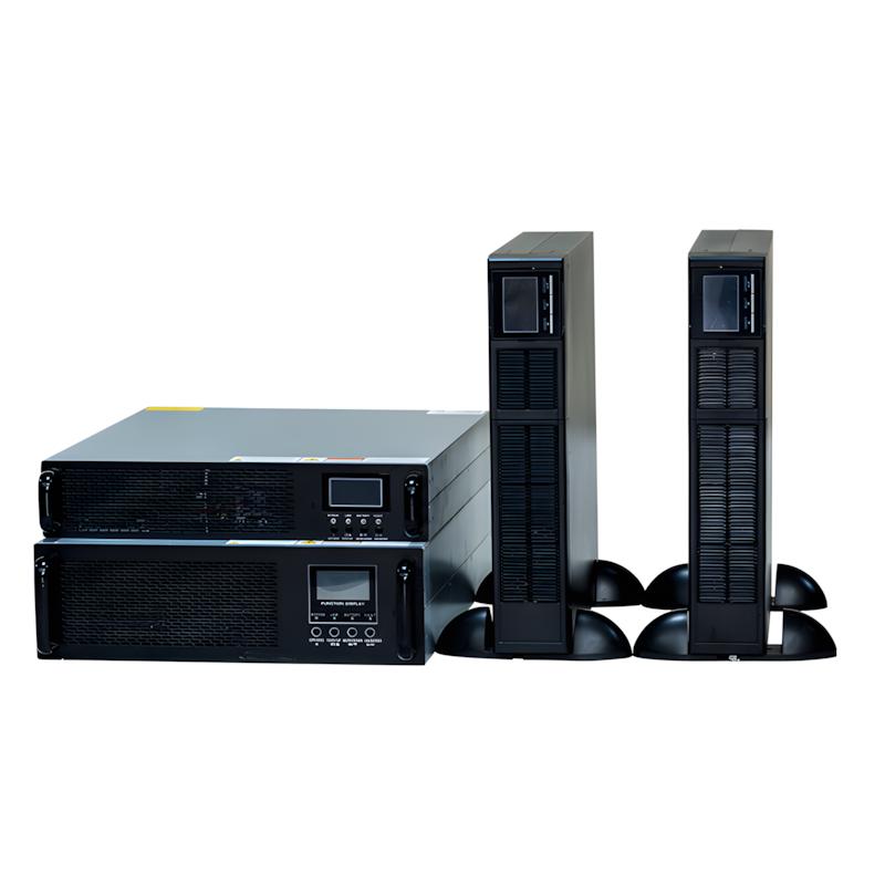
It is a rack-mounted uninterruptible power supply designed for IT equipment, data centers and server rooms. Core functions: ① Provide stable, pure sine wave power to protect equipment from voltage fluctuations, power outages, surges and harmonics; ② Ensure zero downtime during power failures (seamless switch to battery power); ③ Support rack-mounted installation to save space. Working principle: Adopt double-conversion (online) technology—AC input is first converted to DC (rectifier), then DC is converted back to stable AC (inverter) for equipment use; when mains power fails, the battery supplies DC power to the inverter instantly (switching time <2ms), ensuring continuous power supply; the high-frequency design (20kHz~50kHz) makes the UPS smaller, lighter and more energy-efficient than low-frequency models.