Analysis of Transmission Line Fault Handling
As a fundamental component of the power grid, transmission lines are widely distributed and numerous, often exposed to diverse geographical and climatic conditions, making them highly susceptible to faults. Common causes include overvoltage, pollution flashover, insulation damage, tree encroachment, and external damage. Line tripping is one of the most frequent faults in power plant and substation operations, with fault types including single-phase-to-ground, phase-to-phase-to-ground, phase-to-phase, and three-phase short circuits. Among these, single-phase-to-ground faults are the most common, accounting for over 95% of all line faults.
1. Transmission Line Fault Analysis
Faults can be classified as transient or permanent:
Permanent faults are typically caused by equipment defects or broken insulators, where the fault persists until repaired.
Transient faults arise from insulator flashovers, surface discharges due to fog or snow, wind-blown debris, tree branches, or animal contact, which may self-clear after a short time.
Statistics show that transient faults account for 70%–80% of all line faults, making them the most frequent.

1.1 Main Causes of Line Tripping
(1) Tower Collapse: Usually occurs during severe weather such as storms or tornado-like winds, where high winds cause structural failure or collapse of transmission towers.
(2) Lightning-Induced Tripping: During thunderstorms, direct lightning strikes or induced overvoltages can cause flashovers on lines, one of the primary causes of tripping.
(3) External Damage: Includes illegal construction, stacking of materials, excavation, stone quarrying, tree planting, unauthorized attachments, and theft of power facilities within the right-of-way, all of which threaten line safety.
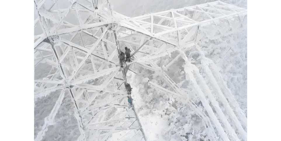
(4) Conductor and Ground Wire Icing: In winter, ice accumulation increases mechanical load, altering conductor sag. Severe icing can damage hardware, break insulator strings, or even cause tower collapse or conductor breakage, leading to tripping.
(5) Conductor Galloping: When horizontal winds blow across conductors that have become non-circular due to ice, aerodynamic forces may induce low-frequency, high-amplitude self-excited oscillations—known as galloping. Galloping can cause phase-to-phase short circuits, especially in vertically arranged lines.
(6) Bird-Related Flashovers: In areas with high bird populations, flocks roosting on tower cross-arms may deposit droppings on insulator strings, reducing insulation strength. Under wet conditions (rain, fog), this can lead to flashovers and single-phase-to-ground faults.
(7) Pollution Flashover: Industrial soot and exhaust pollutants deposit on insulator surfaces, degrading insulation performance. In humid conditions (fog, rain, dew), this can trigger flashovers and line tripping.

1.2 Analysis of Line Tripping Incidents
(1) Permanent Faults: Provided relay protection meets the four key requirements (selectivity, speed, sensitivity, and reliability) and circuit breakers have sufficient interrupting capacity, system stability is generally not severely affected. In such cases, forced re-energization (strong send) can be attempted, with protection systems expected to correctly isolate the faulted line. Years of operational experience have shown no cases where failed strong sends led to cascading outages or expanded incidents.
(2) Foreign Object Contact: Often results in conductor strand breakage. If only a few strands are broken, the line can typically continue operating for a period under controlled load.
(3) Lightning Strikes: Sometimes, due to prolonged insulation recovery time, the reclosing time delay may not be sufficient, leading to unsuccessful reclosing. However, operational experience and statistics indicate that lightning damage is often minor, and the success rate of forced re-energization remains high.
(4) Failed Reclosing after Cascading Trip: The cause can be identified through protection action records and technical analysis. Once confirmed, the拒动 (failed-to-trip) circuit breaker can be manually opened, followed by forced re-energization of the line.
2. General Procedures for Line Fault Handling
(1) If a transient fault occurs and the circuit breaker trips and successfully recloses, operating personnel should record the time, check and document the operation of line protection and fault recorders, verify no internal equipment damage, and report to dispatch.
(2) For lines equipped with synchronizing devices, if a circuit breaker trips and voltage is confirmed on the line under acceptable synchronizing conditions, on-site personnel may perform synchronization and reconnection without waiting for dispatch orders, then report to dispatch.
(3) If a circuit breaker or protection failure causes a cascading trip, operating personnel must identify and isolate the fault point before re-energizing. Re-closing is strictly prohibited until the cause is identified and the fault isolated, to prevent further escalation.
(4) If a circuit breaker trips during protection maintenance (with the line energized), with no fault recording and no tripping on the opposite side, all secondary circuit work should be halted immediately. The cause should be investigated, reported to dispatch, and after appropriate measures are taken, a test re-energization may be attempted (possibly due to unremoved protection channels or accidental contact).
(5) After fault handling, personnel must record detailed incident logs, circuit breaker trip counts, and compile a comprehensive on-site report based on trip records, protection and automatic device actions, event logs, fault recordings, and microprocessor protection printouts.
(6) Upon a line trip, personnel must immediately determine:
Which protections or automatic devices operated;
Whether the breaker successfully reclosed;
Whether it was single-phase or multi-phase tripping, and which phase;
Whether voltage remains on the line;
Whether fault recording is available;
Whether event prints, central signals, and protection panel indications are correct;
Whether microprocessor protection generated a report;
On-site inspection of the actual breaker position and all line-side equipment for signs of short circuits, grounding, flashovers, broken conductors, broken porcelain, explosions, or oil spraying—regardless of whether reclosing occurred.
(7) If a fault causes a breaker trip and reclosing fails, operating personnel should record the time, reset alarms, check and document protection and fault recorder actions, confirm no plant equipment damage, set the breaker control switch to the "after-trip" position, and log the number of trips. Subsequent actions may include:
For critical lines or special periods (e.g., major power supply assurance), after a visual inspection of the breaker reveals no abnormalities, disable reclosing and attempt one forced re-energization;
Under normal conditions, the line maintenance unit should inspect key sections (e.g., crossings over roads, railways, bridges, rivers, residential areas) to confirm no abnormalities. After disabling reclosing, attempt a test re-energization. If forced re-energization fails, step-by-step voltage escalation may be applied if conditions allow;
If the fault is accompanied by obvious signs (e.g., fire, explosion), immediate forced re-energization is prohibited. Equipment must be inspected first. After successful re-energization, line current should be controlled, and the maintenance unit notified immediately to inspect the line and obtain fault data promptly;
For single-source load lines, if tripping occurs and reclosing fails, on-site personnel may immediately attempt one forced re-energization without waiting for dispatch orders, then report to dispatch.


