
Pêşnûna û Prînsîpa ya Relêya Impedansa (Relêya Deyarka)
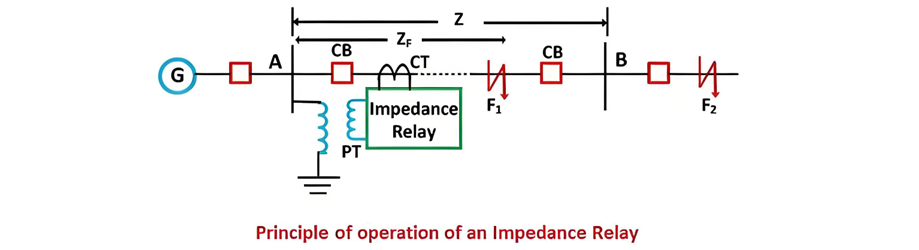
Relêya impedansa, ya da relêya deyarka, yek e cihaz a parastina dike ku ji vêgerîya elektrîkî (impedansa) yên naveroka naverokê û pozisyonê relêyayê re têne. Operasyonê we dike li ser pêwistkirina impedansa yên naverokan û berhevkirin bi çendîna birêvehat.
Mecelalîna Kar
Prînsîpa Operasyona
Li ser karê normal, rêsaya dîmend/bar (impedansa) jêrê rêza relêyayê qebultir e. Di demê naverokan de (mînace F1 li ser AB), impedansa berdest û bi rêza destnîşanê werin. Mînak, heke relêya bike dike bi parastina naverokê AB bi impedansa normal Z, naveroka impedansa berdest kirin, relêya guhêreka barkirinê derbas dide. Heke naveroka dijwar herêm parastina be (mînace dijwar AB), impedansa zêdetir bimîne û relêya nikarekê were.
Xusyayên Operasyona
Relêya du anîvan ênînîn:

-K3 nîşan dide efektê resfêlan relêyayê. Li ser karê normal, net torq = 0 bi dîmend û bar.

Heke efektê kontrolê resfêlan were negirt, ewekar ekwasyonê ye

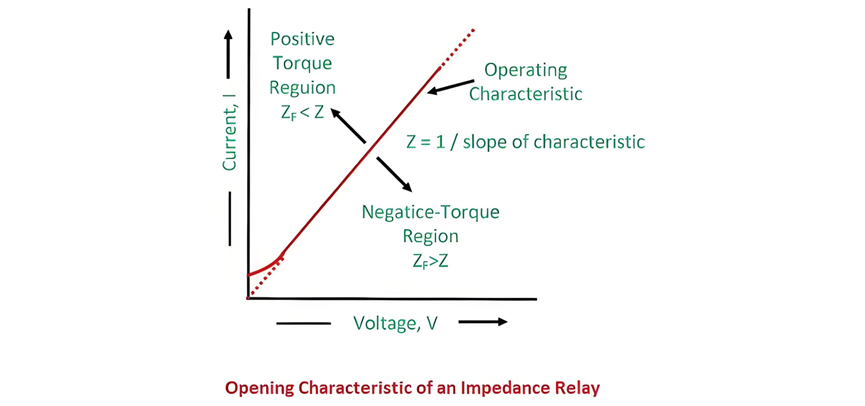
Wekar nîşan dide xusyayên operasyona bi dîmend û bar; xeta kesandî nîşan dide impedansa naverokê const.
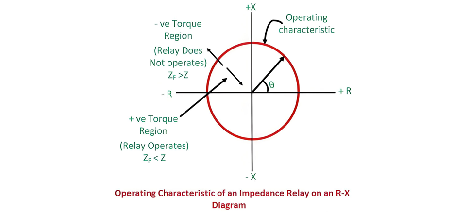
Wekar dijîn nîşan dide xusyayên operasyona relêya impedansa. Herêm dijwar xeta xusyayên operasyona torqa positîf e, ku impedansa naverokê bi îmkanîya zêdetir bimîne, operasyon relêyayê destnîşan dide. An jî, herêm torqa negatîf (jêr xeta) nîşan dide impedansa naverokê bi îmkanîya berdest bimîne, relêya nikarekê were. Ev destnîşana pêşnûnê bi berhevkirina impedansa pêwistkirî bi rêza destnîşanê, parastina tevaniyên parastina naverokan di sisteman elektrîkî de.
Radiusi çember nîşan dide impedansa naverokê; angle X-R nîşan dide pozisyon vektoral. Impedansa < radius = torqa positîf (relêya operasyon bigire); impedansa > radius = torqa negatîf (relêya nikarekê were). Ev destnîşana vizualî destnîşanê pêşnûnê raporî di sisteman elektrîkî de.
Ev relêya dike di kategorî relêyan hêsanî de.
Relêya Induksyon Elektromagnetîk
Torqa di relêya de ji induksyon elektromagnetîk dîmend û bar, ku bi yek din pêwistkirin, derbas dide. Di circuitê de, Solenoid B—bi transformatora potansiyala (PT)—torqa saetî neşînin, plunger P2 bi derbas dibe. Resfêla bi P2 force restorasyon neşînin, torqa mekanîk saetî neşînin.
Solenoid A, bi transformatora kurrenta (CT) şîn dibe, torqa deflaktand (pick-up) saetî neşînin ku plunger P1 bi derbas dibe. Li ser şertên normal, kontakên relêya vekir in. Di demê naverokan de di herêmê parastin, kurrenta sisteman bêdawêtin, torqa Solenoid A’ biger û torqa restorasyon Solenoid B’ berdest. Ev imbalans armên balans relêyayê werin, kontakan bişopandin bi parastina destnîşan dide. Designê hêsanîkarê pêşnûnê naverokan bi berhevkirina torqên elektromagnetîk û mekanîk.
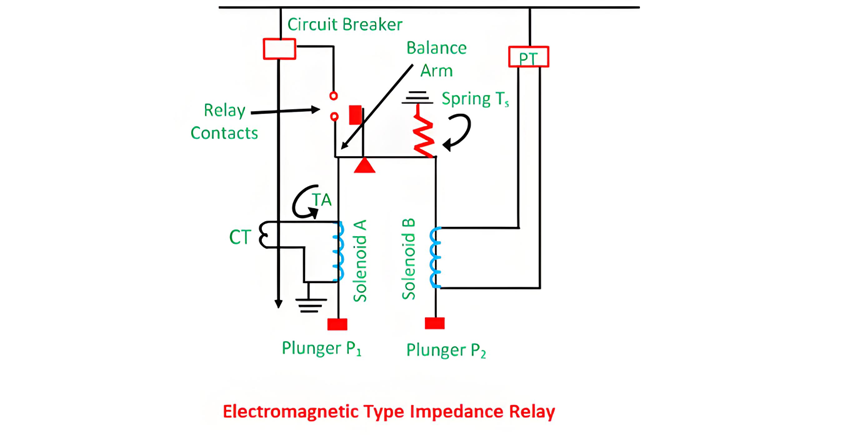
Force ku solenoid A (element kurrenta) neşînin proporsiyonal e , wanke force ku solenoid B (element dîmend) neşînin proporsiyonal e . Bi vê yekê, relêya operasyon bigire heke force ku ji kurrenta derbas dibe bi force ku ji dîmend derbas dibe.

Konstanta k1 û k2 depend bi ampere-turns solenoidên du û rasyo transformatorekan instrument. Setên relêya bi tappings li ser coils destnîşan dibe.
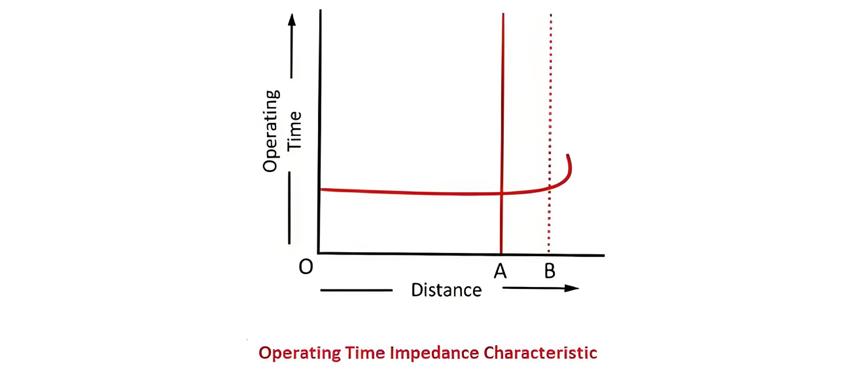
Li ser grafik xusyayên operasyona, axis y nîşan dide dema operasyona relêyayê, axis x nîşan dide impedansa. Notable, dema operasyona relêyayê bi sabit (nîşan dide aksiyon instantane) li ser impedansa di herêm parastina destnîşan. Li ser distance destnîşan (corresponding to the set impedance), dîmend û bar values stabilize; beyond this point, the measured impedance theoretically becomes infinite, meaning the relay remains inactive for faults outside its protective scope. This linear relationship between impedance and operating time ensures reliable, rapid fault detection within the defined zone.
Induction Type Impedance Relay
The circuit diagram of an induction-type impedance relay is illustrated below. This relay incorporates both current and voltage elements, featuring an aluminium disc that rotates between electromagnets.
The upper electromagnet contains two distinct windings: the primary winding is connected to the secondary coil of a current transformer (CT), while the secondary winding is linked to a potential transformer (PT). The current setting of the primary winding can be adjusted via a plug bridge positioned beneath the relay, allowing for precise calibration of the relay’s sensitivity. The voltage element, energized by the PT, generates a magnetic field that interacts with the current-derived field from the CT.
This interaction induces eddy currents in the aluminium disc, producing a torque that drives its rotation. Under normal operating conditions, the disc remains stationary due to balanced torques; during a fault, the current surge unbalances the torques, causing the disc to rotate and trigger the relay contacts. This design ensures reliable impedance-based fault detection in power systems.
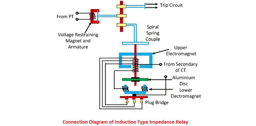
The electromagnets in the relay are connected in series, with their induced fluxes generating rotational torque that drives the aluminium disc. A permanent magnet provides both controlling and braking torque to stabilize the disc’s motion.
Under normal operation, the force on the armature exceeds the torque from the induction element, keeping the trip contacts open. When a system fault occurs, the current through the electromagnets surges, causing the aluminium disc to rotate. The disc’s rotational speed is directly proportional to the fault current, winding a spring as it turns. This rotational motion gradually overcomes the restraining torque from the permanent magnet.
Once the disc’s rotation reaches a critical threshold (corresponding to the preset impedance), the trip contacts close, initiating the protective response. This design ensures that the relay reacts swiftly to faults while maintaining stability during normal operation, with the permanent magnet providing essential control over the disc’s acceleration and braking to prevent false tripping.
The rotation angle of the relay's disc relies on the armature force, which is directly proportional to the applied voltage. Hence, voltage dictates the rotation angle.
Time-Characteristic of High-Speed Impedance Relay
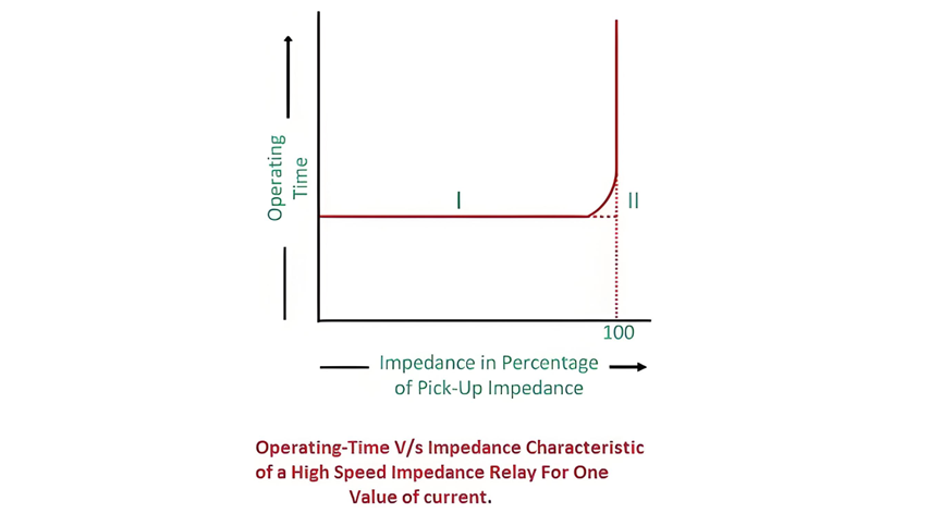
The figure depicts that the relay remains inactive for values exceeding 100% of the pickup threshold. Curve 1 represents the actual operational characteristic, while Curve 2 offers a simplified model of Curve 1. This design ensures rapid response to faults within the preset range while maintaining stability under normal conditions. The relay's high-speed operation is critical for minimizing damage in power systems, with the simplified curve facilitating easier implementation and analysis in protective relay settings.
Drawbacks of Plain Impedance Relay
The following are the key disadvantages of impedance relays:


