Relé ng Distansiya sa Uri ng Impedance

Definisyong at Prinsipyo ng Impedance Relay (Distance Relay)
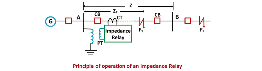
Ang impedance relay, na kilala rin bilang distance relay, ay isang voltage-controlled na protective device na kung saan ang operasyon nito ay depende sa elektrikal na distansya (impedance) sa pagitan ng punto ng kaparangan at posisyon ng instalasyon ng relay. Ito ay gumagana sa pamamagitan ng pagsukat ng impedance ng may kaparangan na seksyon at paghahambing nito sa pre-set na threshold.
Mekanismo ng Paggana
Prinsipyo ng Paggana
Sa normal na operasyon, ang ratio ng voltage-to-current (impedance) ay nananatiling itaas sa threshold ng relay. Sa panahon ng kaparangan (halimbawa, F1 sa linya AB), ang impedance ay bumababa sa ibaba ng setting. Halimbawa, kung ang relay ay nakainstalo upang protektahan ang linya AB na may normal na impedance Z, ang kaparangan ay nagbabawas ng impedance, na nag-uutos sa relay na tripin ang breaker. Kung ang kaparangan ay nasa labas ng protektadong zone (halimbawa, malayo pa sa AB), ang impedance ay nananatiling mataas, at ang relay ay nananatiling hindi aktibo.
Karakteristik ng Paggana
Ang relay ay binubuo ng dalawang pangunahing komponente:

-K3 kumakatawan sa spring effect ng relay. Sa normal na operasyon, net torque = 0 sa mga halaga ng V at I.

Kung ang epekto ng spring control ay nababalewala, ang ekwasyon ay naging

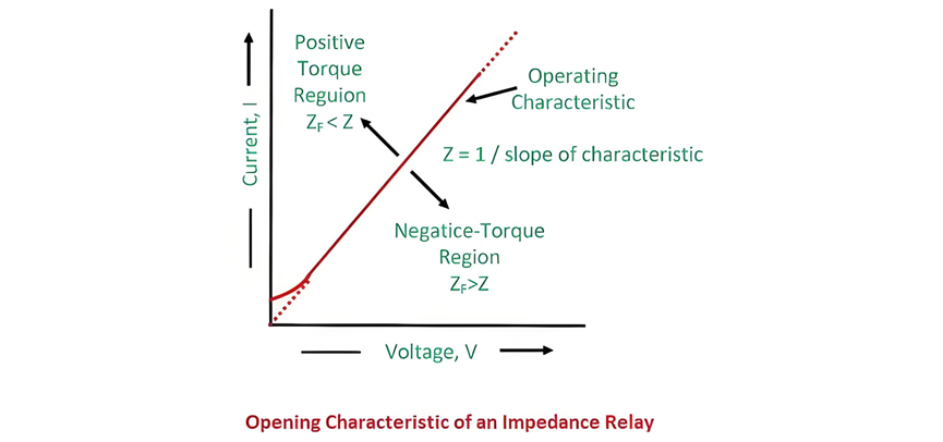
Ang larawan ay nagpapakita ng mga karakteristik ng paggana kasama ang voltage at current; ang dashed line ay nagpapahiwatig ng constant line impedance.
Ang sumusunod na larawan ay nagpapakita ng karakteristik ng paggana ng impedance relay. Ang rehiyon sa itaas ng linya ng karakteristik ay kinakatawan ang positibong torque, kung saan ang line impedance ay lumalampas sa impedance ng may kaparangan na seksyon, na nag-uutos ng paggana ng relay. Sa kabaligtaran, ang negatibong torque region (sa ilalim ng linya) ay nagpapahiwatig na ang fault impedance ay lumalampas sa line impedance, na nagpapanatili ng hindi aktibo ang relay. Ang pagkakaiba-iba na ito ay nagbibigay ng precise na deteksiyon ng kaparangan sa pamamagitan ng paghahambing ng sukatin na impedance laban sa pre-set na threshold, na nag-aalamin ng reliable na proteksyon sa power systems.
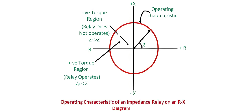
Ang radius ng bilog ay kumakatawan sa line impedance; ang X-R phase angle ay nagpapahiwatig ng vector position. Impedance < radius = positibong torque (relay operates); impedance > radius = negatibong torque (relay inactive). Ang visual na pagkakaiba-iba na ito ay nag-aalamin ng mabilis na deteksiyon ng kaparangan sa power systems.
Ang relay na ito ay nakategorya bilang high-speed relay.
Electromagnetic Induction Relay
Ang torque sa relay na ito ay nanggagaling sa electromagnetic interactions sa pagitan ng voltage at current, na hinahambing para sa operasyon. Sa kanyang circuit, Solenoid B—powered by a potential transformer (PT)—generates clockwise torque, pulling plunger P2 downward. A spring on P2 applies restraining force, creating clockwise mechanical torque.
Solenoid A, excited by a current transformer (CT), produces clockwise deflecting (pick-up) torque that moves plunger P1 downward. Under normal conditions, relay contacts stay open. During a protective zone fault, surging system current increases Solenoid A’s torque while reducing Solenoid B’s restoring torque. This imbalance rotates the relay’s balance arms, closing contacts to initiate protection. The design ensures rapid response to faults via torque comparison between electromagnetic and mechanical forces.
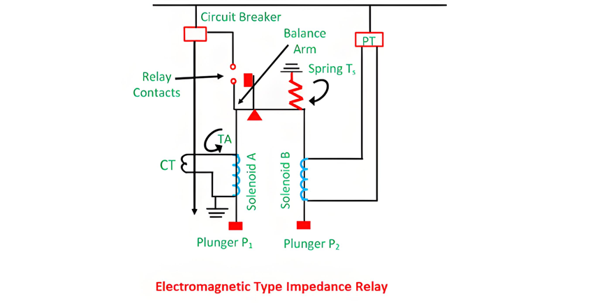
The force exerted by solenoid A (the current element) is proportional to , while that from solenoid B (the voltage element) is proportional to . As a result, the relay will activate when the current-derived force exceeds the voltage-derived force.

The constants k1 and k2 depend on the ampere-turns of the two solenoids and the ratios of the instrument transformers. Relay settings can be adjusted via tappings on the coils.
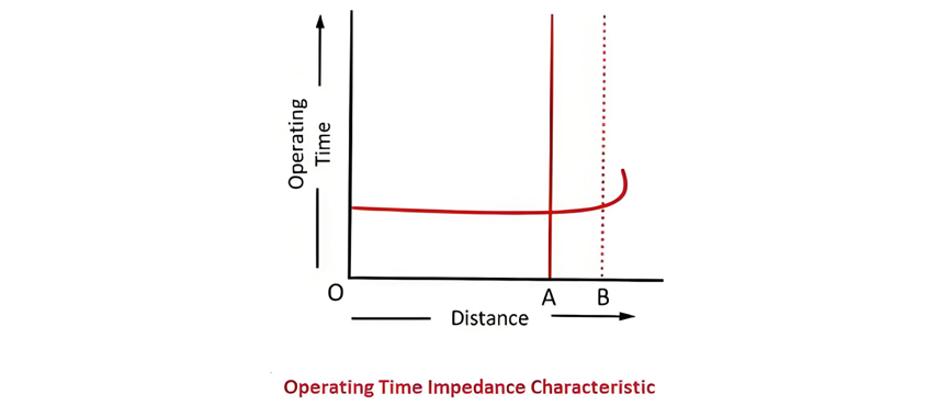
On the characteristic curve, the y-axis denotes the relay’s operating time, while the x-axis represents impedance. Notably, the relay’s operating time remains constant (indicating instantaneous action) for impedances within the preset protection zone. At the predetermined distance (corresponding to the set impedance), voltage and current values stabilize; beyond this point, the measured impedance theoretically becomes infinite, meaning the relay remains inactive for faults outside its protective scope. This linear relationship between impedance and operating time ensures reliable, rapid fault detection within the defined zone.
Induction Type Impedance Relay
The circuit diagram of an induction-type impedance relay is illustrated below. This relay incorporates both current and voltage elements, featuring an aluminium disc that rotates between electromagnets.
The upper electromagnet contains two distinct windings: the primary winding is connected to the secondary coil of a current transformer (CT), while the secondary winding is linked to a potential transformer (PT). The current setting of the primary winding can be adjusted via a plug bridge positioned beneath the relay, allowing for precise calibration of the relay’s sensitivity. The voltage element, energized by the PT, generates a magnetic field that interacts with the current-derived field from the CT.
This interaction induces eddy currents in the aluminium disc, producing a torque that drives its rotation. Under normal operating conditions, the disc remains stationary due to balanced torques; during a fault, the current surge unbalances the torques, causing the disc to rotate and trigger the relay contacts. This design ensures reliable impedance-based fault detection in power systems.
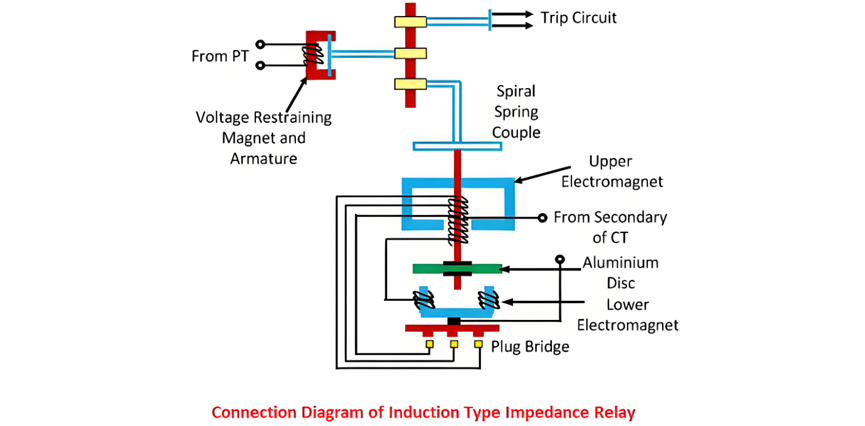
The electromagnets in the relay are connected in series, with their induced fluxes generating rotational torque that drives the aluminium disc. A permanent magnet provides both controlling and braking torque to stabilize the disc’s motion.
Under normal operation, the force on the armature exceeds the torque from the induction element, keeping the trip contacts open. When a system fault occurs, the current through the electromagnets surges, causing the aluminium disc to rotate. The disc’s rotational speed is directly proportional to the fault current, winding a spring as it turns. This rotational motion gradually overcomes the restraining torque from the permanent magnet.
Once the disc’s rotation reaches a critical threshold (corresponding to the preset impedance), the trip contacts close, initiating the protective response. This design ensures that the relay reacts swiftly to faults while maintaining stability during normal operation, with the permanent magnet providing essential control over the disc’s acceleration and braking to prevent false tripping.
The rotation angle of the relay's disc relies on the armature force, which is directly proportional to the applied voltage. Hence, voltage dictates the rotation angle.
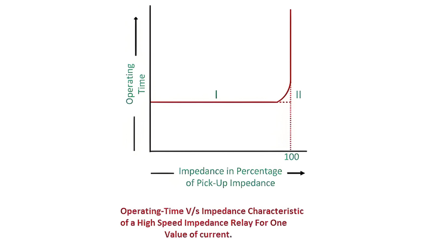
Time-Characteristic of High-Speed Impedance Relay
The figure depicts that the relay remains inactive for values exceeding 100% of the pickup threshold. Curve 1 represents the actual operational characteristic, while Curve 2 offers a simplified model of Curve 1. This design ensures rapid response to faults within the preset range while maintaining stability under normal conditions. The relay's high-speed operation is critical for minimizing damage in power systems, with the simplified curve facilitating easier implementation and analysis in protective relay settings.
Drawbacks of Plain Impedance Relay
The following are the key disadvantages of impedance relays:


