• Product
  • Suppliers
  • Manufacturers
  • Solutions
  • Free tools
  • Knowledges
  • Experts
  • Communities
Search


Power Transformer Fault Detection & Maintenance | -Ensure Safe Operation

Noah
Noah
Field: Design & Maintenance
Australia

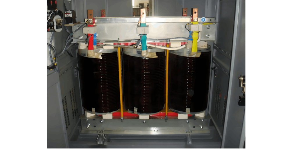
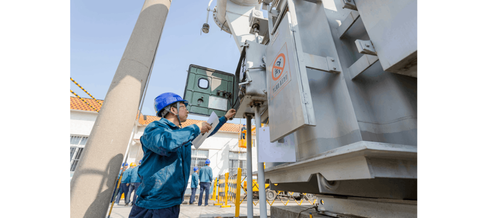
Power transformer fault detection and repair typically require operation by experienced and qualified technical personnel. Below are some common steps for power transformer fault detection and maintenance:

I. Check the transformer’s input and output voltage, current, temperature, and other parameters to ensure they are within normal ranges.

  • Carefully read the transformer’s instruction manual to understand its rated voltage and current, temperature limits, and other special requirements.

  • Use a multimeter to test voltage and current on both the input and output sides of the transformer. During testing, first set the multimeter to an appropriate range, then connect the probes to the transformer’s input and output terminals, and record the voltage and current values.

  • Check the transformer’s temperature. Using a thermometer or infrared thermal imager, measure key components according to the manual or actual conditions. The temperature should be within the allowable range, and temperatures on the input and output sides should be comparable.

  • Inspect the transformer’s insulation condition. Use a multimeter or a dedicated insulation resistance tester to measure the insulation resistance between the windings and ground. Confirm whether the insulation resistance meets the required values as specified in the manual or based on actual conditions.

  • Check the transformer’s oil level, oil quality, and oil temperature. The oil level should be within the normal range, the oil quality should be good, and the oil temperature should be within acceptable limits. Address any abnormalities immediately if detected.

Checking the transformer’s input/output voltage, current, and temperature parameters is crucial for ensuring normal operation and extending the transformer’s service life.

II. Inspect the transformer winding connections for correctness, secure joints, and absence of poor contact.

  • First, review the transformer’s wiring diagram to confirm that connections on both sides comply with standards, including proper cable selection, securely fastened terminals, and correct joint configurations.

  • Examine the wiring box, terminal box, and other connection areas to ensure connections are stable and reliable, joints are secure, and there are no signs of overheating, oxidation, or physical damage.

  • Use tools such as a multimeter to check the winding connections. Test voltage or current transformation to verify correct connections and detect issues like poor contact or short circuits.

  • If possible, perform a power-on test and observe the operational status and changes in electrical parameters to confirm the integrity of wiring and connections.

Appropriate tools and testing methods should be selected based on site conditions, with necessary maintenance and adjustments performed as needed.

III. Inspect the transformer’s cooling system, including fans, water cooling units, and cooling oil, to ensure normal operation.

  • Inspect the fan system: First, verify whether the transformer is equipped with a fan system. If so, check that the fans are operating normally. You can place your hand near the fan inlet to confirm airflow.

  • Inspect the water cooling system: If the transformer uses water cooling, check that the cooling water flows freely and that discharge pipes are not blocked. Inspect from the water inlet of the cooling unit.

  • Inspect the cooling oil: For oil-cooled transformers, check the oil level and oil quality. Add oil if the level is low; replace the oil if its quality has degraded.

  • Inspect the heat sinks: Check the transformer’s heat sinks for dust accumulation or blockages, and clean them if necessary.

Note: Power must be disconnected before inspection to ensure safety.

IV. Inspect external insulation components, such as insulators, bushings, and seals, for damage or defects.

  • Inspect surface insulation materials: Check external insulation materials (e.g., rubber, plastic) for damage, aging, or deterioration. Replace immediately if any issues are found.

  • Inspect support insulator bricks: If the transformer has support insulator bricks, verify they are intact with no cracks or detachment.

  • Check grounding: Ensure the grounding connection between the transformer enclosure and earth is secure and free of looseness.

  • Check labeling: Verify that external labels (e.g., rated voltage, current) are clear, legible, and correctly marked.

During inspection, power must be disconnected and the equipment discharged in advance to ensure safety. Report any issues to qualified technicians immediately.

V. Perform partial discharge (PD) testing to assess the transformer’s partial discharge performance and insulation condition.

Partial discharge testing helps evaluate the transformer’s PD performance and insulation status, enabling early detection and resolution of potential faults. The specific steps are as follows:

  • Preparation: Select appropriate instruments and sensors, and connect and configure them according to instructions.

  • Clean the surface: Clean the transformer’s surface thoroughly to remove dirt and moisture, which could otherwise affect measurement accuracy.

  • Conduct the test: Securely attach sensors to the transformer’s surface and monitor partial discharge signals in real time, ensuring the instrument detects any changes in partial discharge current. Test duration varies based on equipment capacity and required precision, typically ranging from several hours to several days.

  • Analyze results: Analyze the data, compare PD levels at different measurement points, eliminate interference, locate abnormal areas, identify fault causes and severity, and determine whether repair or component replacement is needed.

  • Address faults: If abnormal PD is detected, promptly determine the cause and take corrective actions. Common measures include enhancing insulation, reinforcing local areas, repairing, or adjusting operations to eliminate partial discharge.

VI. If faults are identified, repair or replace faulty components such as winding coils or insulation materials.

VII. After repairs, perform functional testing to ensure the transformer’s performance meets requirements.

Note: Power transformers are large, high-voltage equipment. Strict adherence to safety procedures during operation is essential to ensure the safety of personnel and equipment.

Give a tip and encourage the author!
Recommended
What Are Combined Transformer Standards? Key Specs & Tests
Combined Instrument Transformers: Technical Requirements and Testing Standards Explained with DataA combined instrument transformer integrates a voltage transformer (VT) and a current transformer (CT) into a single unit. Its design and performance are governed by comprehensive standards covering technical specifications, testing procedures, and operational reliability.1. Technical RequirementsRated Voltage:The primary rated voltages include 3kV, 6kV, 10kV, and 35kV, among others. The secondary v
Edwiin
10/23/2025
What Are the Types of Reactors? Key Roles in Power Systems
Reactor (Inductor): Definition and TypesA reactor, also known as an inductor, generates a magnetic field within the surrounding space when current flows through a conductor. Therefore, any current-carrying conductor inherently possesses inductance. However, the inductance of a straight conductor is small and produces a weak magnetic field. Practical reactors are constructed by winding the conductor into a solenoid shape, known as an air-core reactor. To further increase inductance, a ferromagnet
James
10/23/2025
35kV Distribution Line Single-Phase Ground Fault Handling
Distribution Lines: A Key Component of Power SystemsDistribution lines are a major component of power systems. On the same voltage-level busbar, multiple distribution lines (for input or output) are connected, each with numerous branches arranged radially and linked to distribution transformers. After being stepped down to low voltage by these transformers, electricity is supplied to a wide range of end users. In such distribution networks, faults such as phase-to-phase short circuits, overcurre
Encyclopedia
10/23/2025
Why Upgrade to Maintenance-Free Transformer Breathers?
Maintenance-Free Moisture Absorption Technology for Oil-Immersed TransformersIn traditional oil-filled transformers, the temperature control system causes thermal expansion and contraction of insulating oil, requiring the sealing gel chamber to absorb significant moisture from the air above the oil surface. The frequency of manual silica gel replacement during patrols directly impacts equipment safety—delayed replacement can easily lead to oil degradation. Maintenance-free moisture absorbers rev
Felix Spark
10/23/2025
Related Products
Send inquiry
Download
Get the IEE Business Application
Use the IEE-Business app to find equipment, obtain solutions, connect with experts, and participate in industry collaboration anytime, anywhere—fully supporting the development of your power projects and business.