Steam Dryness Fraction

03/21/2024

WechatIMG1854.jpeg

What is Dryness Fraction?

Steam is said to be dry saturated when at that particular pressure its temperature is equal to the boiling point. It is difficult to produce dry saturated steam in practice and steam will often contains water droplets. So steam generated in the drum of the boiler is often wet and contains some moisture. If the moisture content of the steam is 7% by mass, then the dryness fraction of the steam is said to be 0.93 and that means the steam is only 93% dry.
Evaporation Enthalpy of wet steam is expressed as a product of specific
enthalpy (hfg) and dryness fraction (x). Heat content of the wet steam and dry saturated steam are different. Dry saturated steam is having higher heat content (useable energy) than the wet steam.

Actual Enthalpy of Evaporation
Actual total Enthalpy of wet steam
Where, hf is Liquid Enthalpy.
Density of water is higher than that of the steam, so the specific volume of the water is far lesser than that of the specific volume of the steam.
Thus the droplets of water in the wet steam will occupy negligible-space and the specific volume of the wet-steam is less than that of the dry steam and given by the formula:
Actual specific volume = x vg
Where, vg is the specific volume of dry saturated steam

Steam Phase Diagram

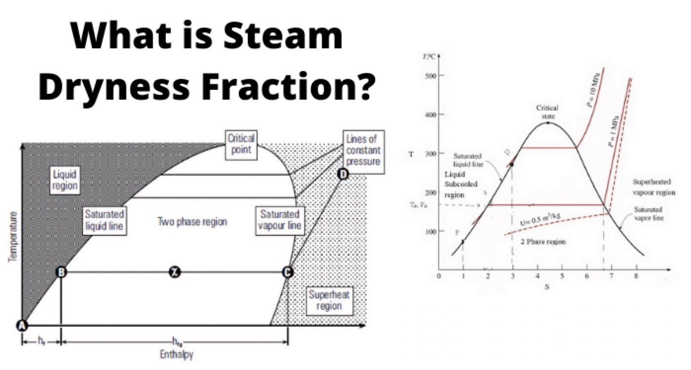
Relation of enthalpy and temperature corresponding to different pressure range is graphically represented in Phase Diagram.
enthalpy curve

Liquid Enthalpy (hf) on Phase Diagram

When water is heated from 0oC to its saturation temperature at atmospheric pressure it follows the saturated liquid line until it has received all its liquid enthalpy hf and is represented by (A-B) on Phase diagram.

Enthalpy of Saturated Steam (hfg)

Any further heat addition results in change in phase to saturated steam and is represented by (hfg) on phase diagram i.e B-C

Dryness Fraction (x)

When heat is applied then the liquid start changing its phase from liquid to vapour and then the dryness fraction of the mixture starts increasing i.e moving towards unity. In the phase diagram dryness fraction of the mixture is 0.5 at exactly mid of the line B-C. Similarly at point C on the phase diagram dryness fraction value is 1.

Line C-D

Point C is in the saturated vapour line, any further heat addition results in increasing the steam temperature i.e beginning of steam super-heating represented by line C – D.

Liquid Zone

Region towards left side of the saturated liquid line.

Super Heat Zone

Region towards right side of the saturated vapour line.

Two Phase Zone

Area between the saturated liquid and saturated vapour line is mixture liquid and vapour. Mixture with varied dryness fractions.

Critical Point

It is the Apex point where saturated liquid and saturated vapour lines meet. Enthalpy of evaporation diminishes to zero at critical point, it means that water changes directly to steam at critical point and thereafter.
Maximum temperature which liquid can attain or exist is equivalent to critical point.

Critical Point Parameters

Temperature 374.15oC, Pressure 221.2 bar, values above this are super-critical values and are useful in increasing the efficiency of the Rankine Cycle.

Flash Steam

What is Flash Steam?

Flash steam is produced when water pressure is reduced from high to a low pressure, then the water is at higher temperature than that of saturation temperature at low pressure. Thus this excess heat energy is released at low pressure in the foam of flashing and the steam thus produced is “Flash Steam”.
flash steam formation

Flashing of Steam

It is the excess energy or enthalpy available (due to fall in pressure) will flashes/evaporate some portion of the water/condensate when pressure falls.
Amount of Flash steam produced is given by the formula:
hf at 6 bar = 697.22 kJ/Kg
hf at 0 bar = 417.5 kJ/Kg
hfg at 0 bar = 2258 kJ/Kg
Flash steam generation for the condensate for values as given in Figure:1 = 0.124 Kg of steam/per Kg of water
OR
= 12.4 %

Flash Steam Effects

Following are the areas where Flash steam effect should be given due consideration other it may lead to water hammer:

  • Condensate-receiver tank vent sizing

  • Steam-traps discharge piping.

  • Condensate return line sizing.

Statement: Respect the original, good articles worth sharing, if there is infringement please contact delete.

Hello,I'm Wdwiin. A decade of hands-on experience in electrical engineering, specializing in high-voltage systems, smart grids, and renewable energy technologies. Passionate about technical exchange and knowledge sharing, committed to interpreting industry trends with professional insights to empower peers. Connection creates value—let’s explore the boundless possibilities of the electrical world together!

What is the difference between a dielectric and an insulator?
Dielectrics and insulators are distinguished primarily by their applications. One of the main differences is that a dielectric can store electrical energy by becoming polarized in an electric field, whereas an insulator resists the flow of electrons to prevent current conduction. Other key differences between them are outlined in the comparison chart below.Definition of DielectricA dielectric material is a type of insulator that contains few or no free electrons. When subjected to an electric fi
08/30/2025
What losses occur during operation of the transformer? How to reduce losses?
Transformers experience various types of losses during operation, primarily categorized into two main types: copper losses and iron losses.Copper LossesCopper losses, also known as I²R losses, are caused by the electrical resistance of the transformer windings—typically made of copper. As current flows through the windings, energy is dissipated in the form of heat. These losses are proportional to the square of the load current (I²R), meaning they increase significantly with high
Rockwell
08/29/2025
Cable Fault Detection, Testing, Location and Repair
I. Methods for Cable Testing and Inspection:Insulation Resistance Test: Use an insulation resistance tester to measure the insulation resistance value of the cable. A high insulation resistance value indicates good insulation, while a low value may suggest insulation problems requiring further investigation.Voltage Withstand Test: Apply a high-voltage test using a high-voltage tester to verify whether the cable can withstand high voltage under its rated operating conditions. Under normal circums
08/29/2025
Cable Quality Inspection and Cable Detection & Testing
Power cable quality inspection and cable testing are conducted to ensure that the cable's quality and performance meet specified requirements, thereby guaranteeing the safe and stable operation of power systems. Below are some common contents of power cable quality inspection and cable testing:Visual Inspection: Check the cable surface for physical defects such as damage, deformation, or scratches to ensure the cable's exterior is intact.Dimensional Measurement: Measure dimensional parameters su
08/29/2025
Inquiry
Download
IEE-Business is dedicated to serving the personnel in the global power industry.
Join IEE-Business, not only can you discover power equipment and power knowledge, but also canhnd like - minded friends!