

Dema ku heta pîçeyên din dikin induktor û lêkê factorê ya çalakî, wek Hay’s bridge yekem dikar a bi serastî bibe di dema ku factorê ya çalakî yekêm bigireke ji 10, Maxwell’s bridge yekem dikar a bi serastî bibe di dema ku factorê ya çalakî be di navbera 1 û 10 de, û Anderson bridge dikar a bi serastî bikar bibe di dema ku induktor be di navbera mikro Henry û several Henry de. Naha nîneka li Owen’s Bridge?.
Ji bo vê pirsgirêka werazok birayê ye. Mîna pîçeya dîkina duhê ku bi serastî dikare induktor bigere di navbera berd de. Pîçeya dîkina ku dikare wê bike di navnîşandina Owen’s bridge.
Ew AC bridge e wek Hay’s bridge û Maxwell bridge ku standart capacitor, induktor û variable resistors re bikaranîna AC sources ji bo excitation. Hêza studiya bike Owen’s bridge circuit di detail de.
An Owen’s bridge circuit is given below.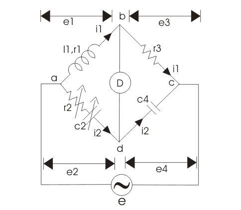
AC supply is connected at a and c point. The arm ab is having inductor having some finite resistance let us mark them r1 and l1. The arm bc consists of pure electrical resistance marked by r3 as shown in the figure given below and carrying the current i1 at balance point which is same as the current carried by arm ab.
The arm cd consists of pure capacitor having no electrical resistance.The arm ad is having variable resistance as well as variable capacitor and the detector is connected between b and d. Now how this bridge works? this bridge measures the inductor in terms of capacitance. Let us derive an expression for inductor for this bridge.
Here l1 is unknown inductance and c2 is variable standard capacitor.
Now at balance point we have the relation from AC bridge theory that must hold good i.e.
Putting the value of z1, z2, z3 and in above equation we get,
Equating and then separating the real and the imaginary parts we get the expression for l1 and r1 as written below:
Now, there is a need to modify the circuit, in order to calculate the incremental value of inductance. Given below is the modified circuit of Owen’s bridge: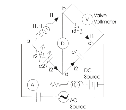
A valve voltmeter is placed across the resistor r3. The circuit is fed from both AC and DC source in parallel. The inductor is used to protect DC source from very high alternating current and the capacitor is used to block direct current from entering the AC source. The ammeter is connected in series with battery to measure the DC component of current while the AC component can be measured from the reading of the voltmeter (which is not sensitive to DC) connected across the resistance r3.
Now at the balance point we have, incremental inductor l1 = r2r3c4
also inductor
Therefore incremental permeability is
N is the number of turns, A is the area of flux path, l is the length of flux path, l1 is incremental inductance.
Let us mark drop across arm ab, bc, cd and ad as e1, e3, e4 and e2 respectively as shown in the above figure. This will help us to understand the phasor diagram well.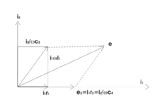
In general the most lagging current (i.e. i1) is chosen as reference in order to draw phasor diagram. Current i2 is perpendicular to current i1 as shown and drop across inductor l1 is perpendicular to i1 as it is an inductive drop while the drop across capacitor c2 is perpendicular to i2. At balance point e1 = e2 which is shown in the figure, now resultant of all these voltage drops e1, e2, e3, e4 will give e.
The for inductor l1 that we have derived above is quite simple and is independent of frequency component.
This bridge is useful for the measurement of inductor over wide range.


