1. Pêşnûmûn
Di dêrhevkirina cihazên bingehîn de, sernavên ên meheme hatine tehdît di navbera bi tevahî û tevahîyên atmosferîk de. Sernavên şokan, veqetî sernavên şokanên oksidî (MOAs) bi xasên nayînî-ampere nehatîn yekêm, ku performansa berbi, kapasîtiya barandaziya mezin û dayîna derbasên kerkirî yên zor dike. Lê, destpêkirina berbi da ku MOAs bi serbexsera têkiliya tevahîyên bingehîn, kaliteta partî, rêzikên çêk û çevreserên derve, ya ku MOAs ji bo hevîna naveroka an patêk kirin, hewceyên bilindkirina, hesabkirina û parastina îlimîyeyan.
Pergala vê makaleya li gorêngî rengkirina çendî MOA-yan 10 kV-an di herêmekê de ye. Analîz dike ku sernavên şokanên patêk pir hemî ji modelê yek sazgeriyê ne. Se MOA-yan bi fese reng û du MOA-yan bi fese serast ji modelê wê sazgeriya werdigire û test kirin bi tenê li gorêngî rastî û pêşkeftin.
2. Pêşnûmûn Rengkirina
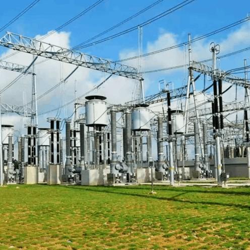
Sernavên şokanê patêk di rêzikên 10 kV-yan de di herêmekê de yên 35 kV-yan de. Di dema çimkaniyê de rengkirina pir dirêj e, û têkiliya naveroka/rangka substation-ê tune werek têkilî yên fese reng sernava şokan. Cin pesan sernava şokan tune werek têkilî yên serparastî û rangka serdar.
Pas instalasyonê di şertê, testên handover (ji bo testkirina direzyan, testkirina voltya DC 1 mA, û testkirina barandazî di 0.75 jî yên 1 mA DC) hate kirin, hemî bi neticeyên qebûl kirin.
3. Analîz Tirîjkirina Rengkirina
Se MOA-yan bi fese reng (No.1, No.2, No.3) werdigire; du MOA-yan bi fese serast (No.4, No.5) test û werdigirin bi tenê li gorêngî bila, bi tenê li gorêngî rastî û pêşkeftin.
3.1 Agahdariya Plakname Nederbas
Lêst se MOA-yan bi fese reng û du MOA-yan bi fese serast: 4 roja sazkerdina bet tune, lê tune rojname; 1 rojname bet tune, lê tune roja sazkerdina; agahdariya din dikarin bi tenê li gorêngî serast be.
Plakan bi tenê li gorêngî serast be bi tenê li gorêngî serast be bi tenê li gorêngî serast be. Tune roja sazkerdina/rojnameyan serbestkirina hesabkirina dema serparastî û tarasîya kaliteta, ke bi tenê li gorêngî serast be serbestkirina rêzikên derbasên biryarî.
3.2 Varistoran Hemin Pirsek
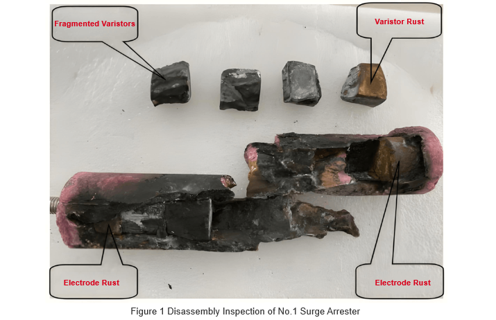
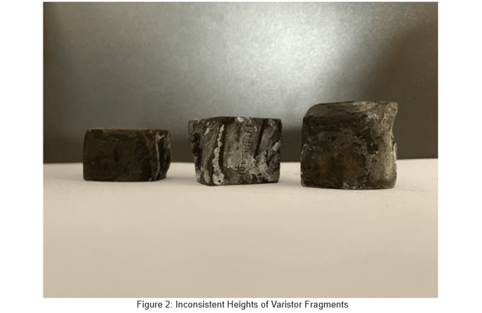
Werdigirina No.1 MOA reng dike: 6 varistoran di du elektrodan de, bi nişaneyên têkildar û pûr beyaz di çendî surfaceyan de; basa serrostina surfaceyan yekem û serostina, varistoran bi forma nederbas, bi tenê li gorêngî serast be. Bîtanên 18 mm, 20 mm, 23 mm, û 25 mm. Se varistoran bi arkên derbas (wateyên di circlekan derbasên disc-yan/annular-yan varistoran). Pirsekên serbast bi tenê li gorêngî serast be di MOA-yan bi fese reng yên din.
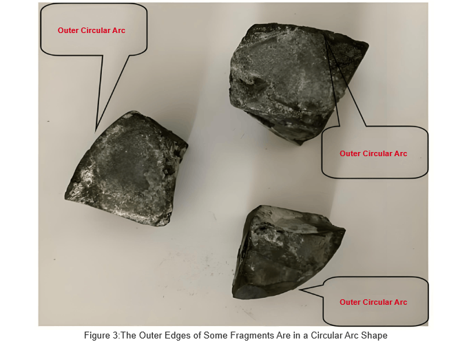
No. 5 MOA serast werdigirin (tune serbexser di processan de, neticeyan di Fig. 4 de). Li navenda: 5 varistoran + 3 metal gasket. Varistoran bi surfaceyan serrostina yekem û serostina, bi forma nederbas, bi tenê li gorêngî serast be: 3 piece ~22mm bîtan, 1 20mm, 1 17mm. 3 piece bi arkên derbas (di circlekan derbasên disc/ring-yan varistoran); 2 bi arkên navendî (di circlekan navendî yên derbasên ring-yan varistoran).
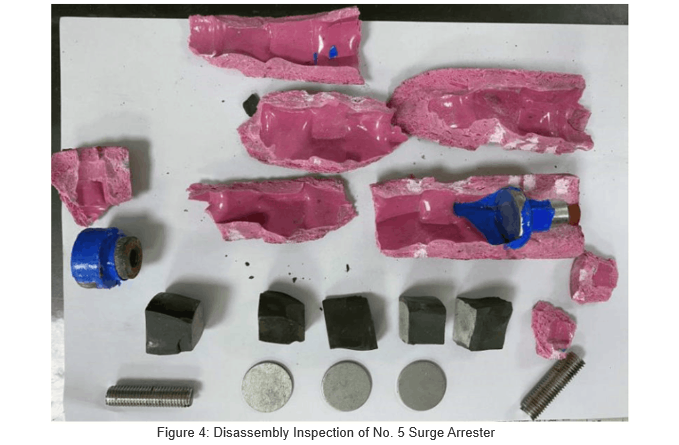
Varistoran di standard metal-oxide surge arrestersan de discs, rings, an cylinders derbas. Dimensionan bi tenê li gorêngî serast be bi tenê li gorêngî serast be (voltya residual/reference), gradient potensiyel, kapasîtiya barandaziya, raw materials, û firing processes. Ji ber core assembly, her varistor bi full tests (power-frequency, DC, high-current impulse, square-wave, etc.) hate test kirin. Tenê pieceyan qebûl kirin.
Werdigirina dike ku MOA-yan wan bi varistoran nederbas: countên varistor/metal gaskets nederbas di unitên same-model de; formên nederbas, thicknesses varying, û arcs outer uneven. Wan core bi fragments of conventional varistors (specs/electrical params different), not 10 kV standard ones. Comparison of faulty vs. normal phases confirms this is a factory defect, not fault-induced.
Such varistors have subpar electrical performance. Uneven contact areas worsen overvoltage resistance, current-carrying capacity, and stability—easily causing breakdowns during line surges.
3.3 Poor Sealing of Composite Jacket
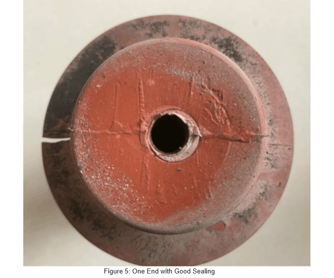
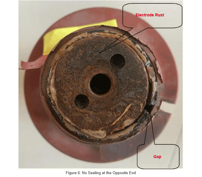
Disassembling No. 3 faulty arrester: one end of the composite jacket seals well with the electrode (Fig. 5); the other end lacks cast sealing. Only a little sealant fills the electrode-arc-shield gap—ineffective for protection, causing gaps and severe electrode rust (Fig. 6).
This poor sealing stems from inadequate casting in production, not faults.
The composite jacket has no casting seal on one side of the arc-isolating cylinder, and the threaded surface of the electrode block is severely rusted. This shows that even with sealant, moisture can seep into the arc-isolating cylinder through thread gaps. During operation, moisture adhering to the varistor core assembly surface increases leakage current and resistive components, causing severe heat. Long-term operation leads to rising temperatures inside the arc-isolating cylinder, possibly melting and bursting the cylinder wall, gradually deteriorating the surge arrester's operational quality.
 When inspecting No. 4 surge arrester, uneven thickness of the composite jacket was found at one electrode end. A micrometer measured the thickest part at 4.985 mm and the thinnest at only 0.275 mm, as shown in Figure 7. The figure also shows the center electrode column perforation of the jacket is not a standard circle, indicating poor sealing here.
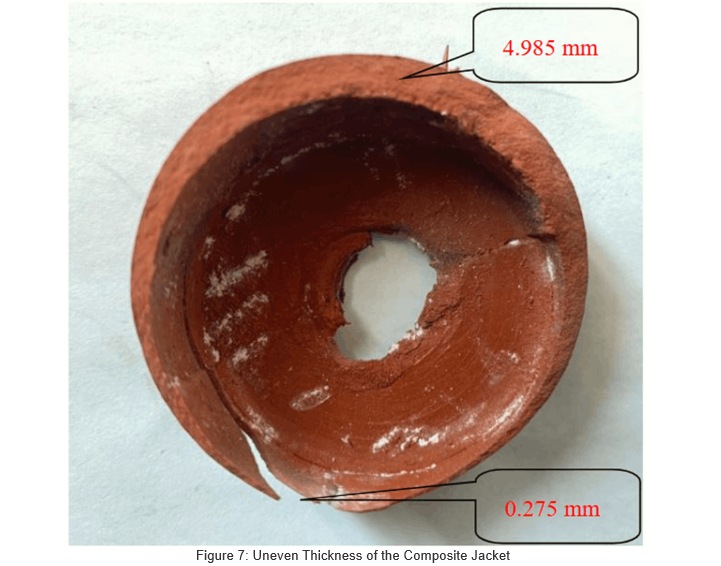
The composite jacket is mainly made of silicone rubber. Its uneven thickness results from poor process control and eccentricity during the vulcanization stage of production. For conventional 10 kV surge arresters, the composite jacket has a uniform thickness of 3–5 mm. Over-thin silicone rubber exhibits poor aging resistance and is prone to cracking. It not only allows moisture to penetrate and adhere to the surface of the insulating cylinder, causing moisture-induced faults, but may also impair the external insulation performance of the equipment, becoming a key factor restricting product quality.
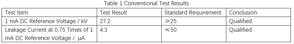
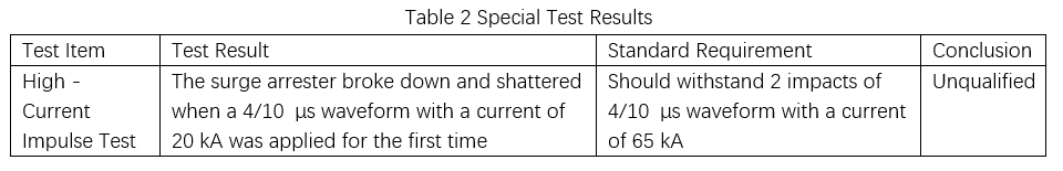
3.4 Qualified in Conventional Tests, Unqualified in Special Tests
DC voltage-related tests were performed on the No. 5 normal surge arrester, with results shown in Table 1.
To verify its over-current withstanding capability, a high-current impulse test was conducted on the No. 4 normal surge arrester. Even when the test impulse current was far below the standard-specified value, the arrester still experienced breakdown and shattering, resulting in a failed test. Detailed data are presented in Table 2.
4. Recommendations
When bidding and procuring surge arresters (especially for distribution networks), clearly define supplier qualifications and technical specs. Choose suppliers with mature processes and good performance; avoid overly low-cost bids.
During acceptance of delivered distribution network arresters, construction and operation units must follow standards like “Five-Pass”. Conduct item-by-item checks, retain factory test reports to ensure qualification rates.
Use provincial material inspection centers’ test platforms. Perform sampling tests (AC/DC, high-current impulse, sealing) for 10 kV arresters to block unqualified products from grid connection.
After installation, before commissioning, strictly follow GB 50150—2016 for on-site tests. Issue standardized reports, archive as required. Ensure full-process data management (production → transport → acceptance → handover test → commissioning). Post-commissioning, enhance patrols/records. In rainy seasons, use infrared imaging. For abnormal heating, power off and replace promptly to prevent fault expansion.