1. Introduction
During power system operation, main equipment faces threats from internal and atmospheric overvoltages. Surge arresters, especially metal oxide arresters (MOAs) with excellent nonlinear volt - ampere characteristics, are key for protection due to their good performance, large current - carrying capacity, and strong pollution resistance. However, long - term exposure to power frequency voltages, along with component quality, manufacturing processes, and external environments, makes MOAs prone to abnormal heating or explosions, requiring scientific identification, judgment, and prevention.
This paper addresses large - scale 10 kV distribution MOA failures in a region. Analysis shows burst arresters concentrate on one manufacturer’s model. Three faulty - phase and two normal - phase MOAs of this model are disassembled and tested to determine causes and countermeasures.
2. Fault Overview
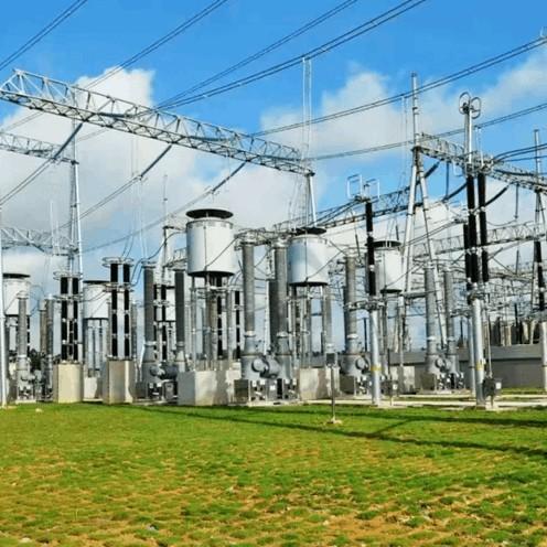
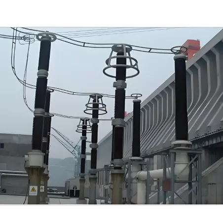
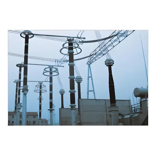
Faulty surge arresters are distributed on the 10 kV distribution lines of a 35 kV substation. Failures are frequent in the thunderstorm season, and the substation’s abnormal/fault records cannot correspond to faulty - phase arresters. The five sampled arresters lack accurate protection action and fault recording information. Lightning location systems show that in 2020, there were 516 lightning strikes within a 10 - km radius centered on this substation.
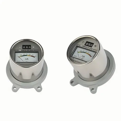
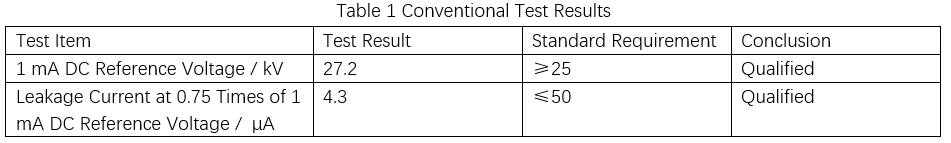
After on - site installation, handover tests were conducted (including insulation resistance testing, 1 mA DC reference voltage testing, and leakage current testing at 0.75 times the 1 mA DC reference voltage), all with qualified results.
3. Failure Cause Analysis
Three faulty - phase arresters (No.1, No.2, No.3) are disassembled; two normal - phase arresters (No.4, No.5) undergo tests and disassembly for comparison, to identify large - scale failure causes.
3.1 Incomplete Nameplate Information
Among three faulty - phase and two normal - phase arresters: 4 have manufacturing dates but no serial numbers; 1 has a serial number but no date; other information is relatively complete.
Nameplates are critical for operation and maintenance personnel to obtain basic equipment information. Missing manufacturing dates/serial numbers hinders service - life calculation and quality tracing, impeding centralized defect management.
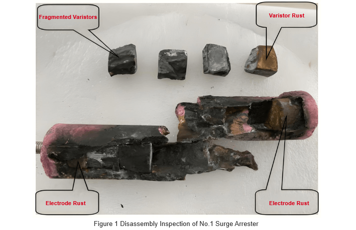
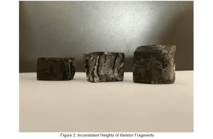
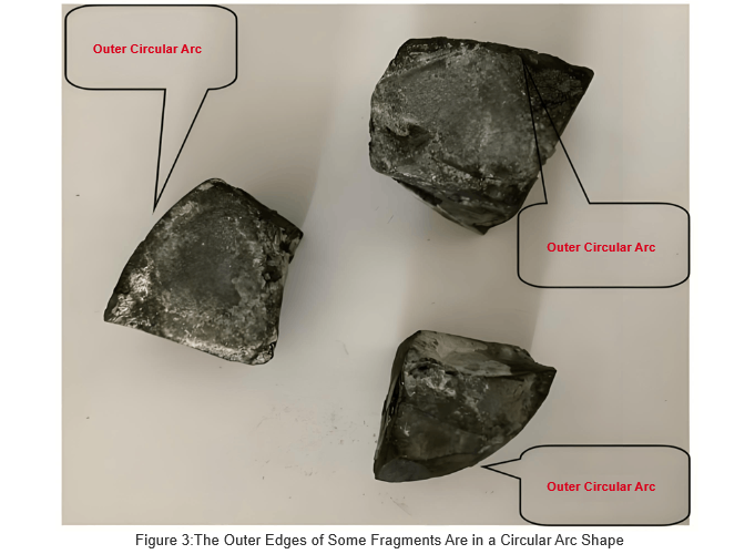
3.2 Varistors Are All Fragments
Disassembly of No.1 faulty arrester reveals: 6 varistors between two electrodes, with burning marks and white powder on some surfaces; except for relatively flat upper/lower surfaces, varistors are irregular in shape, with no uniform size or arrangement. Thicknesses include 18 mm, 20 mm, 23 mm, and 25 mm. Three varistors have regular outer arcs (presumably from the outer circles of complete disc - shaped/annular varistors). Similar issues exist in the other two faulty - phase arresters.
The No. 5 intact surge arrester was disassembled (no damage during process, results in Fig. 4). Inside: 5 varistor pieces + 3 metal gaskets. Varistors have flat top/bottom surfaces, irregular fragments otherwise, similar to others: 3 pieces ~22mm thick, 1 at 20mm, 1 at 17mm. 3 pieces show regular outer arcs (from outer circles of complete disc/ring - shaped varistors); 2 show regular inner arcs (from inner circles of complete ring - shaped varistors).
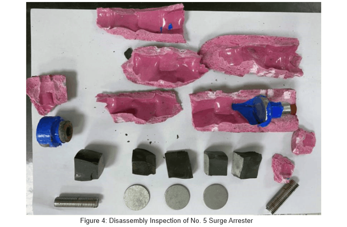
Varistors of standard metal - oxide surge arresters are regular discs, rings, or cylinders. Their dimensions link strictly to voltage ratio (residual/reference voltage), potential gradient, current - carrying capacity, raw materials, and firing processes. Before core assembly, each varistor undergoes full tests (power - frequency, DC, high - current impulse, square - wave, etc.). Only passed pieces are assembled.
Disassembly shows these arresters use unconventional varistors: inconsistent counts of varistors/metal gaskets across same - model units; irregular shapes, varying thicknesses, and uneven outer arcs. Thus, cores are patched from fragments of conventional varistors (different specs/electrical params), not 10 kV standard ones. Comparison of faulty vs. normal phases confirms this is a factory defect, not fault - induced.
Such varistors have subpar electrical performance. Uneven contact areas worsen overvoltage resistance, current - carrying capacity, and stability—easily causing breakdowns during line surges.
3.3 Poor Sealing of Composite Jacket
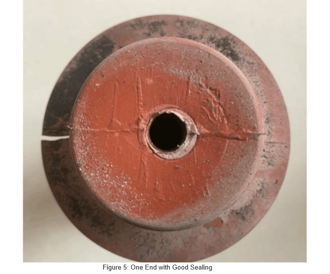
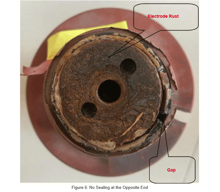
Disassembling No. 3 faulty arrester: one end of the composite jacket seals well with the electrode (Fig. 5); the other end lacks cast sealing. Only a little sealant fills the electrode - arc - shield gap—ineffective for protection, causing gaps and severe electrode rust (Fig. 6).
This poor sealing stems from inadequate casting in production, not faults.
The composite jacket has no casting seal on one side of the arc - isolating cylinder, and the threaded surface of the electrode block is severely rusted. This shows that even with sealant, moisture can seep into the arc - isolating cylinder through thread gaps. During operation, moisture adhering to the varistor core assembly surface increases leakage current and resistive components, causing severe heat. Long - term operation leads to rising temperatures inside the arc - isolating cylinder, possibly melting and bursting the cylinder wall, gradually deteriorating the surge arrester's operational quality.
 When inspecting No. 4 surge arrester, uneven thickness of the composite jacket was found at one electrode end. A micrometer measured the thickest part at 4.985 mm and the thinnest at only 0.275 mm, as shown in Figure 7. The figure also shows the center electrode column perforation of the jacket is not a standard circle, indicating poor sealing here.
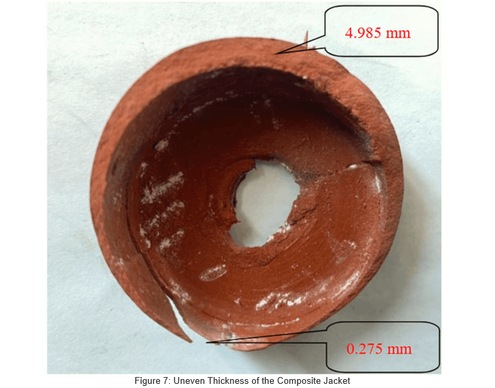
The composite jacket is mainly made of silicone rubber. Its uneven thickness results from poor process control and eccentricity during the vulcanization stage of production. For conventional 10 kV surge arresters, the composite jacket has a uniform thickness of 3–5 mm. Over - thin silicone rubber exhibits poor aging resistance and is prone to cracking. It not only allows moisture to penetrate and adhere to the surface of the insulating cylinder, causing moisture - induced faults, but may also impair the external insulation performance of the equipment, becoming a key factor restricting product quality.
3.4 Qualified in Conventional Tests, Unqualified in Special Tests
DC voltage - related tests were performed on the No. 5 normal surge arrester, with results shown in Table 1.
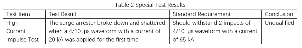
To verify its over - current withstanding capability, a high - current impulse test was conducted on the No. 4 normal surge arrester. Even when the test impulse current was far below the standard - specified value, the arrester still experienced breakdown and shattering, resulting in a failed test. Detailed data are presented in Table 2.
4. Recommendations
When bidding and procuring surge arresters (especially for distribution networks), clearly define supplier qualifications and technical specs. Choose suppliers with mature processes and good performance; avoid overly low - cost bids.
During acceptance of delivered distribution network arresters, construction and operation units must follow standards like “Five - Pass”. Conduct item - by - item checks, retain factory test reports to ensure qualification rates.
Use provincial material inspection centers’ test platforms. Perform sampling tests (AC/DC, high - current impulse, sealing) for 10 kV arresters to block unqualified products from grid connection.
After installation, before commissioning, strictly follow GB 50150—2016 for on - site tests. Issue standardized reports, archive as required. Ensure full - process data management (production → transport → acceptance → handover test → commissioning).Post - commissioning, enhance patrols/records. In rainy seasons, use infrared imaging. For abnormal heating, power off and replace promptly to prevent fault expansion.