1. Regarding GIS, how should the requirement in Clause 14.1.1.4 of the State Grid’s "Eighteen Anti-Accident Measures" (2018 Edition) be understood?
14.1.1.4: The neutral point of a transformer shall be connected to two different sides of the main mesh of the grounding grid via two grounding down conductors, and each grounding down conductor shall meet the thermal stability verification requirements. Main equipment and equipment structures shall each have two grounding down conductors connected to different trunks of the main grounding grid, and each grounding down conductor shall also satisfy the thermal stability verification requirements. The connection leads shall be arranged to facilitate periodic inspection and testing.
Compared with the 2012 edition of the "Eighteen Anti-Accident Measures," the wording was changed from “main equipment and equipment structures should preferably have two grounding down conductors connected to different trunks of the main grounding grid” to “main equipment and equipment structures shall have two grounding down conductors connected to different trunks of the main grounding grid.” This change upgrades the requirement from a recommendatory (“should preferably”) to a mandatory (“shall”) one. Currently, all substations in China have implemented dual grounding down conductors as required. To better protect main equipment, dual grounding down conductors must be mandatorily applied.
Explanation of Clause 14.1.1.4 of the 2018 Edition State Grid “Eighteen Anti-Accident Measures” as it applies to GIS:
GIS is classified as main equipment in a substation and must comply with this clause:
The GIS enclosure and its associated support structures must be equipped with two grounding down conductors, and these two conductors must connect to different trunks of the main grounding grid (to avoid single-point failure leading to loss of grounding);
Each grounding down conductor must pass thermal stability verification (to ensure it will not be damaged by overheating when fault current flows through it);
The layout of the grounding conductors must allow for convenient periodic inspection and testing (to meet operational and maintenance requirements for grounding reliability).
This clause upgrades the 2012 version’s “recommendatory requirement” to a “mandatory requirement.” As a core piece of main equipment, GIS must be configured with dual grounding down conductors to enhance the redundancy and reliability of the grounding system.
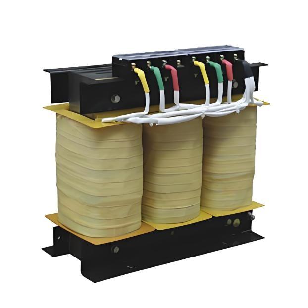
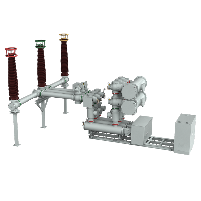
Combined with the on-site situation as shown in the figure below.
For the standalone main equipment shown in the figure above, the requirement for double grounding is relatively straightforward to understand. However, for GIS—where circuit breakers, disconnectors, and other major components are integrated together—interpretations of "double grounding for main equipment" may vary among individuals. In my view, the entire GIS should simply be regarded as one single main equipment unit. The basis for this is as follows:
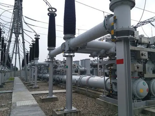
Each bay’s enclosure base and support structure shall have no fewer than two reliable grounding points. Grounding down conductors shall be securely connected, free from corrosion, damage, or deformation, and maintain good electrical continuity. Exposed horizontal grounding busbars shall have additional supports installed at intervals of 0.5–1.5 m, vertical sections at intervals of 1.5–3 m, and bends at intervals of 0.3–0.5 m.
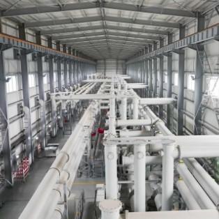
As applied on-site, this is illustrated in the figure below: Points A and B represent the two reliable grounding connections between the base and the main grounding grid. The base is then reliably bonded to the GIS support structure via the jumper at point C. Individual GIS modules are reliably interconnected through jumpers at point D (metal flanges do not require bonding jumpers). This configuration establishes a reliable dual-point grounding system for the entire GIS assembly (with the GIS enclosure itself serving as part of the grounding path).

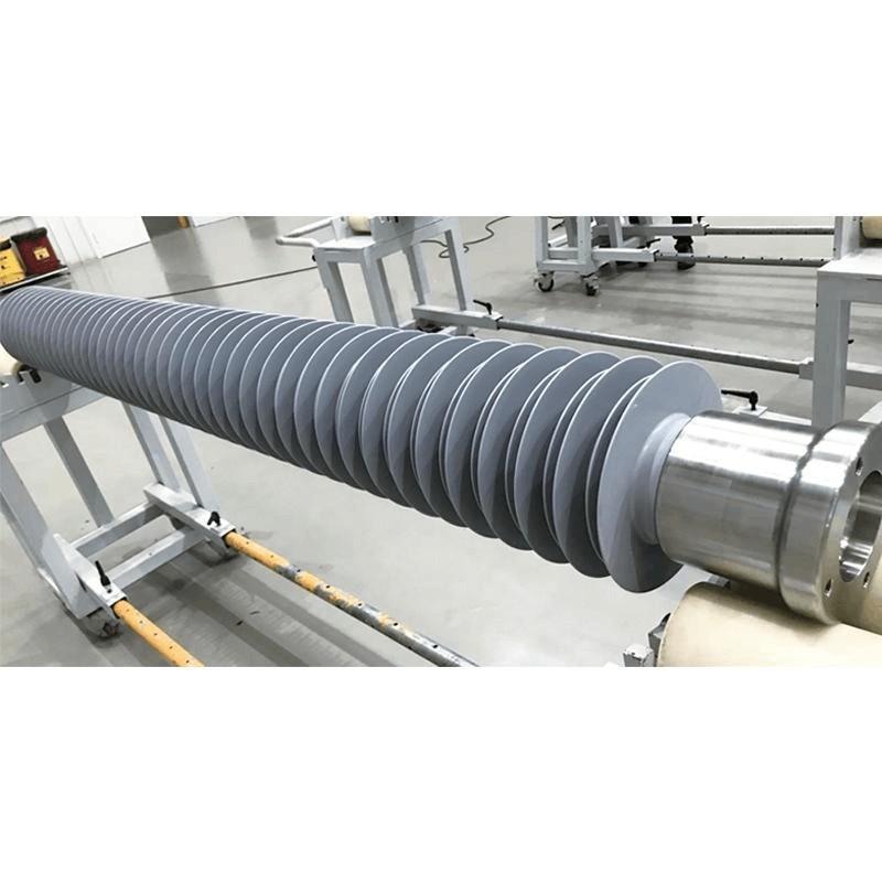
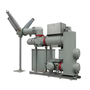
Someone might then ask: "If that’s the case, what is the purpose of all those individual grounding leads on the GIS?" as shown in the figure below:

This leads to the second question:
2. Regarding GIS, how should the requirement for direct grounding be understood?
The figure above shows grounding conductors directly led from different parts of the GIS to dedicated grounding terminals or grounding blocks—rather than relying on the GIS enclosure for grounding. The reason is specified in the following regulation:
“Voltage transformers, surge arresters, and fast grounding switches shall be connected directly to the main grounding grid via dedicated grounding conductors, and shall not be grounded through the enclosure or support structures.”

Looking at the figure above, another question arises:
3. For surge arresters, voltage transformers, and fast grounding switches inside GIS, is there a requirement for dual direct grounding?
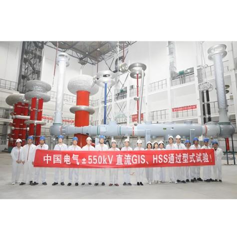
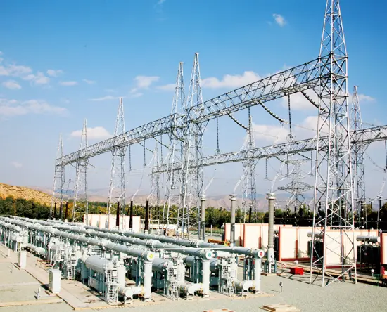
As shown in the figure below:

Regarding the substation shown in the figure above, some experts have pointed out that the fast grounding switch should also use two grounding conductors directly connected to the grounding block. In response to this issue, we specifically consulted the manufacturer, and the manufacturer’s reply stated that there is no requirement for mandatory dual direct grounding—only direct grounding is required, as long as the grounding conductor can carry the required grounding fault current.