• Product
  • Suppliers
  • Manufacturers
  • Solutions
  • Free tools
  • Knowledges
  • Experts
  • Communities
Search


Development and Technical Characteristics of Dry-Type Transformers in Different Regions

Vziman
Vziman
Field: Manufacturing
China

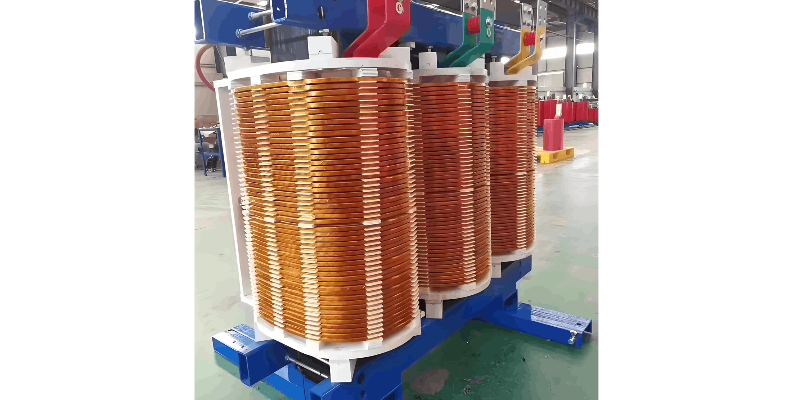
Prior to the 1960s, dry-type transformers primarily employed Class B insulation in open-ventilated designs, with the product model designated as SG. At that time, foil windings were not yet available, so low-voltage coils were typically constructed using multi-strand conductors in layered or spiral configurations, while high-voltage coils adopted a disc-type design. The conductors used were either double glass-fiber-wrapped wires or single glass-fiber-wrapped wires with alkyd enamel coating.

Most other insulation components were made of phenolic glass fiber materials. The impregnation process involved using Class B insulation varnish to impregnate the high- and low-voltage coils at ambient temperature and pressure, followed by medium-temperature drying (with temperatures not exceeding 130°C). While this type of dry-type transformer represented a significant improvement in fire resistance compared to oil-immersed transformers, its performance in terms of moisture and pollution resistance was inadequate.

As a result, production of this type has been discontinued. Nevertheless, the successful design of its electrical, magnetic, and thermal calculations, along with its structural layout, laid a solid foundation for the subsequent development of new Class H insulated open-ventilated dry-type transformers.

In the United States, certain manufacturers, such as FPT Corporation in Virginia, developed dry-type transformers using DuPont's NOMEX® aramid material as the primary insulation. FPT offers two product models: the FB type, with an insulation system rated at 180°C (Class H), and the FH type, rated at 220°C (Class C), featuring coil temperature rises of 115K (125K in China) and 150K, respectively. Low-voltage coils use either foil or multi-strand layered windings, with turn-to-turn and layer-to-layer insulation made of NOMEX®.

High-voltage coils are of the disc type, with conductors wrapped in NOMEX® paper. Instead of conventional spacer blocks between coil discs, comb-shaped spacers are used, effectively halving the peak voltage between discs and significantly enhancing the axial short-circuit strength of the high-voltage coils—though this increases winding complexity and manufacturing time. The high- and low-voltage coils are concentrically wound to improve mechanical strength. Some designs also incorporate NOMEX® insulation boards as spacers and blocks.

The insulation cylinders between high- and low-voltage windings are made from 0.76 mm thick NOMEX® paperboard. The impregnation process employs multiple cycles of vacuum pressure impregnation (VPI) followed by high-temperature drying (reaching 180–190°C). At FPT, these transformers are manufactured with a maximum voltage rating of 34.5 kV and a maximum capacity of 10,000 kVA. This technology has received UL certification in the United States.

In China, some transformer manufacturers have adopted DuPont’s NOMEX® insulation materials and relevant manufacturing specifications (such as HV-1 or HV-2) along with Reliatran® transformer technical standards to produce Class H insulated SG-type dry-type transformers, similar to FPT’s FB type. However, unlike FPT, domestic manufacturers typically impregnate only the coils rather than the entire transformer assembly. Although full-body impregnation provides better overall sealing, it is less visually appealing and requires all product testing to be completed prior to treatment. Additionally, the impregnating varnish is more prone to contamination, making coil-only impregnation a more practical and reasonable choice in the Chinese context.

In Europe, the development of dry-type transformers has taken a more diverse path. In addition to epoxy resin vacuum casting and winding technologies, other types have emerged, including SCR-type non-cast solid-insulated encapsulated transformers and SG-type open-ventilated dry-type transformers similar to those in China. In the 1970s, a Swedish manufacturer developed open-ventilated dry-type transformers using NOMEX® insulation. Later, another manufacturer replaced NOMEX® with glass fiber and DMD, reducing material costs.

The coil structure resembled early Class B insulated products, with multi-strand or foil-wound low-voltage coils and disc-type high-voltage coils. Turn insulation was made of glass fiber, and spacers were ceramic. Other insulation components used modified diphenyl ether resin glass cloth laminates (for cylinders) or modified polyamide-imide laminated glass cloth boards (for cylinders), DMD, SMC, and similar materials. The coil processing method employed VI (vacuum impregnation) without pressure application during impregnation.

Key technical aspects of this process include the proper selection of impregnation varnish (resin) and process parameters, as well as the production of ceramic parts. Ordinary ceramics are brittle, unglazed, susceptible to moisture, and prone to cracking under uneven stress or thermal gradients. Therefore, they must possess very high density and hardness—qualities currently achievable only through imported materials.

Give a tip and encourage the author!
Recommended
What Is MVDC Technology? Benefits, Challenges & Future Trends
Medium-voltage direct current (MVDC) technology is a key innovation in power transmission, designed to overcome limitations of traditional AC systems in specific applications. By transmitting electrical energy via DC at voltages typically ranging from 1.5 kV to 50 kV, it combines the long-distance transmission advantages of high-voltage DC with the flexibility of low-voltage DC distribution. Against the backdrop of large-scale renewable integration and new power system development, MVDC is emerg
Echo
10/23/2025
Why Does MVDC Grounding Cause System Faults?
Analysis and Handling of DC System Grounding Faults in SubstationsWhen a DC system grounding fault occurs, it can be classified as single-point grounding, multi-point grounding, loop grounding, or reduced insulation. Single-point grounding is further divided into positive-pole and negative-pole grounding. Positive-pole grounding may cause misoperation of protection and automatic devices, while negative-pole grounding may lead to failure to operate (e.g., relay protection or tripping devices). On
Felix Spark
10/23/2025
How to Improve Rectifier Transformer Efficiency? Key Tips
Optimization Measures for Rectifier System EfficiencyRectifier systems involve numerous and diverse equipment, so many factors affect their efficiency. Therefore, a comprehensive approach is essential during design. Increase Transmission Voltage for Rectifier LoadsRectifier installations are high-power AC/DC conversion systems requiring substantial power. Transmission losses directly impact rectifier efficiency. Increasing the transmission voltage appropriately reduces line losses and improves r
James
10/22/2025
How Does Oil Loss Affect SF6 Relay Performance?
1.SF6 Electrical Equipment and the Common Problem of Oil Leakage in SF6 Density RelaysSF6 electrical equipment is now widely used in power utilities and industrial enterprises, significantly advancing the development of the power industry. The arc-quenching and insulating medium in such equipment is sulfur hexafluoride (SF6) gas, which must not leak. Any leakage compromises the reliable and safe operation of the equipment, making it essential to monitor the SF6 gas density. Currently, mechanical
Felix Spark
10/21/2025
Send inquiry
Download
Get the IEE Business Application
Use the IEE-Business app to find equipment, obtain solutions, connect with experts, and participate in industry collaboration anytime, anywhere—fully supporting the development of your power projects and business.