Introduction
The LW12 - 500 tank - type SF₆ circuit breaker is a domestic high - voltage circuit breaker. As the operation time increases continuously, frequent failures of the main body and operating mechanism have had a significant impact on the safe and stable operation of the power grid, affecting the power supply reliability and causing the maintenance cost of the circuit breaker to rise year by year. Aiming at the common defects and faults of the LW12 - 500 tank - type SF₆ circuit breaker, this paper puts forward corresponding preventive and control measures, so as to completely eliminate equipment hidden dangers and improve the operation level of the power grid.
Equipment Overview
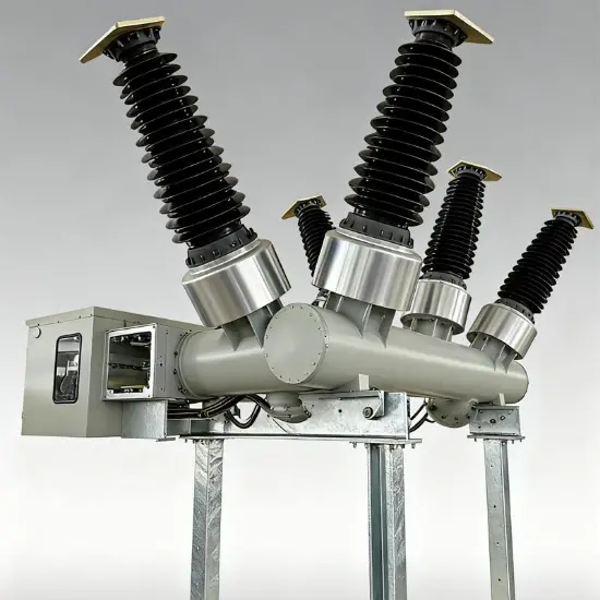
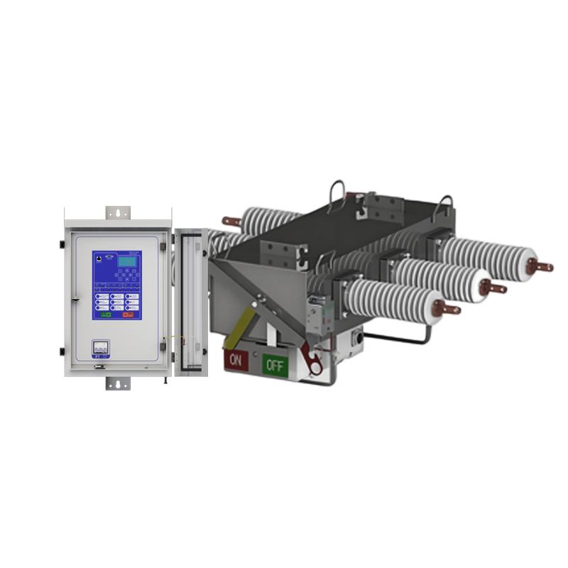
The LW12 - 500 tank - type SF₆ circuit breaker uses SF₆ gas as the insulation and arc - extinguishing medium. The operating mechanism adopts pure hydraulic pressure, and the main components of the hydraulic mechanism are imported from Hitachi. The circuit breaker has a double - break structure, with parallel capacitors installed at both ends of the main break. The parallel capacitors are provided by Murata Company of Japan.
Equipment Service Conditions
There are still many LW12 - 500 tank - type SF₆ circuit breakers in service within the State Grid Corporation system. By the end of 2014, there were 33 such circuit breakers in operation in Jibei Company, 14 of which were equipped with closing resistors, and the operation time was ≥10 years.
Equipment Failure Situations
In September 2002, a single - phase grounding fault occurred in phase B of an LW12 - 500 tank - type SF₆ circuit breaker. The phase B of breakers 5031 and 5032 at a certain substation tripped. The phase B of breaker 5032 reclosed successfully, while the phase B of breaker 5031 failed to reclose. Through inspection, it was found that due to the loosening of the adjusting nut of the pressure switch, the closing lock pressure value changed, resulting in the failure of the circuit breaker to reclose.
From April to June 2004, during the normal equipment maintenance and pre - testing, the LW12 - 500 tank - type SF₆ circuit breakers 5053, 5043 and 5012 at a certain substation showed the phenomenon of refusing to open during operation. The inspection showed that the fault was caused by the deterioration of the hydraulic oil in the operating mechanism, which led to the poor movement of the valve body.
In June 2004, during operation, phase C of the LW12 - 500 tank - type SF₆ circuit breaker 5052 at a certain substation had a fault of internal discharge in the tank due to the peeling off of the silver - plating layer of the pressure cylinder inside the arc extinguish chamber.
In June 2005, when a certain substation carried out the normal power - off opening operation on the LW12 - 500 tank - type SF₆ circuit breaker 5043, the rotating shaft pin of the opening trip latch below the opening electromagnet of the phase B operating mechanism broke, causing the phase B of the circuit breaker not to separate. At the same time, the series resistance in the opening circuit was damaged and desoldered. After inspection, after replacing the damaged latch, opening coil and opening series resistance, the equipment was put back into operation.
In June 2005, when the 2# busbar of a certain substation was powered on, the phase C of the LW12 - 500 tank - type SF₆ circuit breaker 5053 tripped immediately after closing. Inspection found that the deformation of the striker rod caused the first - stage opening valve to fail to reset, and the circuit breaker tripped continuously. It returned to normal after replacing the striker rod.
In May 2006, due to the continuous tripping faults of a certain line, the closing coil of phase B of the LW12 - 500 tank - type SF₆ circuit breaker 5012 was burned out. The inspection showed that the fault was caused by the jamming of the closing latch in phase B, which made the closing coil charged for a long time and caused the burnout.
In July 2007, an internal discharge fault occurred in the tank of phase B of the LW12 - 500 tank - type SF₆ circuit breaker 5031 at a certain substation during operation. The reason was the poor painting process (manual brushing) of the conductive rod inside the bushing. Due to uneven brushing, foreign matters such as brush bristles adhered to the conductive rod, and the brush bristles fell off on the shield, causing the shield to discharge to the inner wall of the tank.
In November 2007, during a fault at Substation 3#, the LW12-500 tank-type SF₆ circuit breaker 5013 experienced multiple opening and closing failures, leading to the escalation of the accident.
In February 2009, during a protection actuation test after a power outage maintenance on the LW12-500 tank-type SF₆ circuit breaker 5012, phase C failed to close. Inspection revealed that the shaft connecting the closing latch and the buckle in the mechanism was inflexible, preventing the latch and buckle from releasing and causing the phase failure to close.
In June 2009, internal flashover occurred in phase A of the LW12-500 tank-type SF₆ circuit breaker 5021 during power transmission after major maintenance. The fault was attributed to sharp corners in the shield assembly and unclean interior of the tank.
In March 2012, after opening, phase A of the LW12-500 tank-type SF₆ circuit breaker 5053 first experienced interrupter breakdown, which then developed into a ground fault. Inspection showed that the degradation of parallel capacitor plates between the interrupters caused the capacitor to burst after breakdown, triggering discharge between the shield and the tank.
In January 2013, after opening, phase B of the LW12-500 tank-type SF₆ circuit breaker 5043 again experienced interrupter breakdown, followed by a ground fault; the 12-second arc between the interrupters in phase A was cleared by the bus differential protection before developing into a ground fault. The fault was similarly caused by degradation of parallel capacitor plates between the interrupters, with capacitor breakdown and bursting triggering shield-to-tank discharge.
Major Defects
Early-production units had poor insulation paint application on the conductive rod inside the bushing (manual brushing process), leaving hidden hazards of internal insulation discharge due to adhering brush bristles, delamination, and peeling of the paint.
The internal surface of the tank had poor insulation paint workmanship, prone to delamination and peeling, causing internal insulation discharge risks; the grading shield inside the tank had poor machining and assembly, with sharp corners and protrusions.
The silver-plated layer on the inner surface of the arc extinguish chamber's pressure cylinder was prone to delamination and peeling.
Poor alignment of moving and stationary contacts or low-quality contact springs caused fragmentation and shedding of arc contact fingers and nozzles.
Degradation of parallel capacitor plates between interrupters posed risks of insulation breakdown.
Unreasonable design of mechanism heating and sealing systems caused ultra-high oil pressure alarms in multiple circuit breakers during seasonal transitions.
Frequent hydraulic mechanism failures, particularly high damage rates of seals and pressure accumulators, reduced mechanism reliability:
Multiple occurrences of "immediate reclosure after opening" or "continuous tripping" due to poor machining of the hydraulic mechanism's primary valve;
Severe degradation of hydraulic oil, leading to frequent pressurization and oil leakage;
Insufficient strength and prone-to-fracture/deformation of some metal parts (e.g., latches) in the operating mechanism due to poor material or machining quality;
Quality issues with pressure accumulators, causing pre-charged pressure drops in multiple units that failed to meet operational requirements after prolonged operation.
Retrofit Measures
The implemented maintenance measures for LW12-500 circuit breakers include:
Replacing the conductive rod inside the bushing with a new type featuring advanced insulation coating technology.
Thorough internal inspection and maintenance of the tank: focusing on checking the internal paint layer, closing resistor assembly, silver-plated layer of the pressure cylinder (replaced if delaminated/peeled), and alignment adjustment of moving/stationary contacts.
Inspection and maintenance of the operating mechanism: including valve systems, pressure accumulators, working cylinders, hydraulic pumps, and complete replacement of hydraulic oil.
Replacing interrupter parallel capacitor plates with improved-process components provided by Japan's Murata Corporation.
Suggested Improvement Measures
To ensure power grid safety and stability, timely maintenance of LW12-type circuit breakers is crucial. However, challenges in spare parts supply and technical services—compounded by the breaker's long-term discontinuation and poor spare parts availability—have made maintenance difficult, with high single-unit overhaul costs approaching those of purchasing new breakers. Considering safety, economy, and technological advancement, overall replacement of LW12-500 tank-type SF₆ circuit breakers is recommended.
Before retirement, strengthen operational condition monitoring and maintenance of LW12-type breakers. Use advanced technologies such as ultrasonic partial discharge detection and SF₆ gas chromatographic analysis to regularly assess internal insulation status under operating voltage, shorten detection cycles, and timely track insulation degradation trends. This enables targeted measures to prevent sudden internal insulation failures during operation.