• Product
  • Suppliers
  • Manufacturers
  • Solutions
  • Free tools
  • Knowledges
  • Experts
  • Communities
Search


Voltage Drop Explained

The Electricity Forum
Field: Publishes Electricity
0
Canada

Voltage drop (VD) occurs when the voltage at the end of a run of cable is lower than at the beginning. Any length or size of wires will have some resistance, and running a current through this dc resistance will cause the voltage to drop. As the length of the cable increases, so does its resistance and reactance increase in proportion. Hence, VD is particularly a problem with long cables runs, for example in larger buildings or on larger properties such as farms. This technique is often used when properly sizing conductors in any single phase, line to line electrical circuit. This can be measured with a voltage drop calculator.

WechatIMG1481.jpeg

Electrical cables carrying current always present inherent resistance, or impedance, to the flow of current. VD is measured as the amount of voltage loss which occurs through all or part of a circuit due to what is called cable "impedance" in volts.

Too much VD in a cable cross sectional area can cause lights to flicker or burn dimly, heaters to heat poorly, and motors to run hotter than normal and burn out. This condition causes the load to work harder with less voltage pushing the current.

How is this solved?

To decrease the VD in a circuit, you need to increase the size (cross section) of your conductors – this is done to lower the overall resistance of the cable length. Certainly, larger copper or aluminum cable sizes increase cost, so it’s important to calculate VD and find the optimum voltage wires size that will reduce VD to safe levels while remaining cost-effective.


How do you calculate voltage drop?

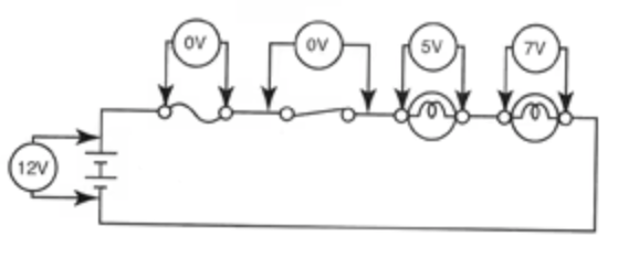
VD is the loss of voltage caused by the flow of current flow through a resistance. The greater the resistance the greater the VD To check the VD, use a voltmeter connected between the poinL where the VD is to be measured. In DC circuits and AC resistive circuits the total of all the voltage drops across series-connected loads should add up to the voltage applied to the circuit (Figure 1).

Each load device must receive its rated voltage to operate properly. If not enough voltage is available, the device will not operate as it should. You should always be certain the voltage you are going to measure does not exceed the range of the voltmeter. This may be difficult if the voltage is unknown. If such is the case, you should always start with the highest range. Attempting to measure a voltage higher than the voltmeter can handle may cause damage to the voltmeter. At times you may be required to measure a voltage from a specific point in the circuit to ground or a common reference point (Figure 8-15). To do this, first connect the black common test probe of the voltmeter to the circuit ground or common. Then connect the red test probe to whatever point in the circuit you want to measure.

To accurately calculate the VD for a given cable size, length, and current, you need to accurately know the resistance of the type of cable you’re using. However, AS3000 outlines a simplified method that can be used.

The table below is taken from AS3000 – it specifies ‘Am per %Vd‘ (amp metres per % voltage drop) for each cable size.  To calculate the VD for a circuit as a percentage, multiply the current (amps) by the cable length (metres); then divide this Ohm number by the value in the table.

For example, a 30m run of 6mm2 cable carrying 3 phase 32A will result in 1.5% drop: 32A x 30m = 960Am / 615 = 1.5%.


WechatIMG1479.png


Give a tip and encourage the author!
Recommended
Why is it difficult to increase the voltage level?
The solid-state transformer (SST), also known as a power electronic transformer (PET), uses voltage level as a key indicator of its technological maturity and application scenarios. Currently, SSTs have reached voltage levels of 10 kV and 35 kV on the medium-voltage distribution side, while on the high-voltage transmission side, they remain in the stage of laboratory research and prototype validation. The table below clearly illustrates the current status of voltage levels across different appli
Echo
11/03/2025
110 kV Transformer Neutral Point Lightning Overvoltage: ATP Simulation & Protection Solutions
There is extensive literature on the analysis of overvoltage at transformer neutral points under lightning surge conditions. However, due to the complexity and randomness of lightning waves, an accurate theoretical description remains elusive. In engineering practice, protective measures are typically determined based on power system codes by selecting appropriate lightning protection devices, with abundant supporting documentation available.Transmission lines or substations are susceptible to l
Felix Spark
10/30/2025
Operation and Fault Handling of High and Low Voltage Power Distribution Systems
Basic Composition and Function of Circuit Breaker Failure ProtectionCircuit breaker failure protection refers to a protective scheme that operates when the relay protection of a faulty electrical device issues a trip command but the circuit breaker fails to operate. It uses the protection trip signal from the faulty equipment and the current measurement from the failed breaker to determine breaker failure. The protection can then isolate other relevant breakers within the same substation in a sh
Felix Spark
10/28/2025
Low-Voltage Distribution Cabinet Maintenance Steps and Safety Guide
Maintenance Procedure for Low-Voltage Power Distribution FacilitiesLow-voltage power distr ibution facilities refer to the infrastructure that delivers electrical power from a power supply room to end-user equipment, typically including distribution cabinets, cables, and wiring. To ensure the normal operation of these facilities and guarantee user safety and power supply quality, regular maintenance and servicing are essential. This article provides a detailed introduction to the maintenance pro
Edwiin
10/28/2025
Related Products
Send inquiry
Download
Get the IEE Business Application
Use the IEE-Business app to find equipment, obtain solutions, connect with experts, and participate in industry collaboration anytime, anywhere—fully supporting the development of your power projects and business.