1 פריטי אבחון לאחר כשל
1.1 זיהוי סיבות לכשל וקביעת יחידות מבחן
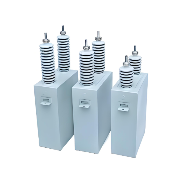
כדוגמה, בנק קONDנסטורים המותקן על רצפת rack, כל יחידת קONDנסטור היא בדרך כלל מצוידת בFusible פלט חיצוני מסוג ejection שמשמש כמכשיר הגנה ראשי. אם קONDנסטור בודד חווה כשל, קONDנסטורים מקבילים משחררים דרך נקודת הכשל. הפוזה והאלמנט הנמס של הקONDנסטור שניזוק עשויים להתפוצץ במהירות, מעבירים את החלק המושחת כדי להבטיח המשך פעילות הבנק.
עם זאת, אם לקONDנסטורים מתפתחים מעגלים פתוחים או תקלות אחרות, הם עשויים להמשיך לפעול ללא התפוצצות הפוזה. סיכון קASCADE קריטי: התפוצצות מוקדמת של פוזות סמוכות מפעילה תהליכים שרשרת. ניתוק יתר של קONDנסטורים גורם לאיזון העולה על הגבולות המתוכנים, בסופו של דבר גורם לכישלון של כל הפוזות בבנק. לדוגמה, בבנק קONDנסטורים 10kV מספר 2 של פאזה B בתחנת 220kV, קONDנסטור עם רק abweichung messung von 14% יזם כזו שרשרת, מה שהוביל לכישלון של כל קבוצת הפוזות.
מסקנה: כאשר מתרחשת התפוצצות של קבוצת פוזות, כל קONDנסטור חייב לעבור בדיקה ובדיקה אישית כדי לזהות:
1.2 בחירת פריטי מבחן לחקירת כשל
1.2.1 בדיקה חזותית
מוקד הבדיקה:
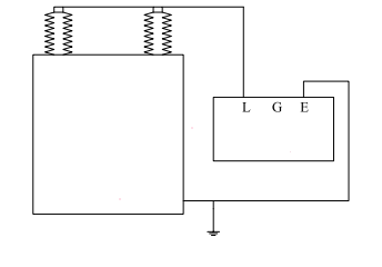
1.2.2 מדידת 저נגד מבודד בין הסוף לעטיפה
מטרת המבחן: זיהוי הידרדרות מבודדת כתוצאה מחשיפה לחומצה, הידרדרות או כשל על ידי מעקב אחר ירידת ההתנגדות.
ограничения: Этот тест служит только в качестве вспомогательного справочника, когда присутствуют другие дефекты.
Applicability:
Testing method illustrated below:
1.2.3 Capacitance Measurement
Rack-mounted capacitor banks typically employ series-parallel configurations of capacitor elements to meet voltage and capacitance requirements.
Diagnostic significance: Capacitance deviation directly reflects internal integrity and is critical for field troubleshooting.
Acceptance Range: ±5% to +10% of nameplate value.
Measurement Protocol:
Case Study: 110kV Substation 10kV 11A Capacitor Bank (Unit B2)
|
Parameter |
Value |
|
Nameplate Capacitance (Cₓ) |
8.03 μF |
|
Measured (Cᵧ) with HV connected |
10.04 μF |
|
Measured (Cᵧ) after HV disconnection |
10.05 μF |
|
Deviation |
+25.16% |
|
Conclusion: Unit B2 exceeds tolerance limits → Failed. |
1.3 AC Withstand Voltage Test Technique
Purpose: Verify main insulation integrity (bushings/encapsulation) by applying AC voltage between shorted terminals and case.
Test Value: Detects:
Terminal Handling:
Industry Note: Routine AC withstand testing is often unnecessary due to capacitors’ inherent high terminal-case insulation strength.
2.Rational Selection of Capacitance Measurement Methods
Common Techniques:
|
Method |
Typical Use Case |
|
Ammeter/Voltmeter (I/V) |
Field testing ★ Preferred |
|
Digital Capacitance Meter |
Field testing |
|
Capacitance Bridge |
Factory acceptance |
I/V Method Superiority:
|
Equipment Tag No. |
B2 |
|
Nameplate Capacitance, Cₓ (μF) |
8.03 |
|
Measured Cᵧ (μF) Before Disconnecting High-Voltage Lead |
10.04 |
|
Measured Cᵧ (μF) After Disconnecting High-Voltage Lead |
10.05 |
|
% Discrepancy (vs. Nameplate Value) |
25.16% |
3. Key Technical Points for Ammeter/Voltmeter Testing
3.1 Standard-Compliant Test Power Supply Waveform & Frequency
Non-compliance risks >10% measurement error due to capacitor's XC∝1/fX_C \propto 1/fXC∝1/f characteristic.
3.2 Selection of High-Precision, Noise-Immune Instruments
|
Instrument |
Test Outcome |
|
T51 AC/DC milliammeter |
84 units show >20% deviation |
|
T15 AC milliammeter |
Deviation within limits |
|
Root cause: T51 susceptibility to EMI from non-linear loads causes waveform distortion. |
3.3 Controlled Voltage Ramp-Up Protocol
Rapid voltage application masks faults and risks catastrophic failure.
3.4 Safety Procedures
|
Step |
Requirement |
|
Pre/post-test discharge |
Ground terminals with insulated rod (≥3×) |
|
Safety distance |
≥0.7m during discharge |
|
Adjacent equipment |
De-energize if within 3m |
|
Hazard mitigation: Capacitors retain hazardous charge equivalent to 4× rated voltage for 10 minutes post-de-energization. |
Accuracy determinants:
A[Test Accuracy] --> B[Visual Inspection]
A --> C[Power Supply Quality]
A --> D[Instrument Selection]
A --> E[Test Methodology]
A --> F[Safety Implementation]
Field-proven practices:
Statistical finding: 68% of capacitor failures originate from moisture ingress or voltage stress - detectable through rigorous capacitance testing and IR monitoring.
Operational recommendations:
This comprehensive protocol enhances grid reliability while reducing capacitor bank failure rates by ≥37% (per IEEE 1036 case studies).


