• Product
  • Suppliers
  • Manufacturers
  • Solutions
  • Free tools
  • Knowledges
  • Experts
  • Communities
Search


SAFE-DELAY Safety Relay

  • SAFE-DELAY Safety Relay
  • SAFE-DELAY Safety Relay
  • SAFE-DELAY Safety Relay

Key attributes

Brand Switchgear parts
Model NO. SAFE-DELAY Safety Relay
Rated frequency 50/60Hz
Series SAFE

Product descriptions from the supplier

Description

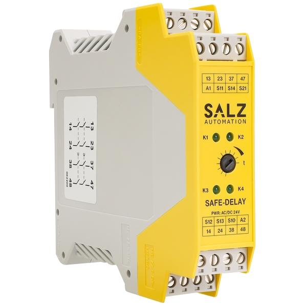
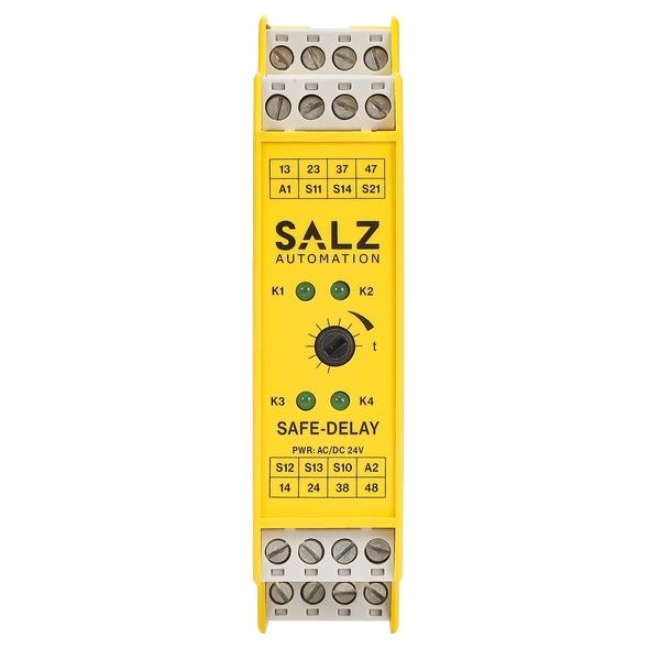
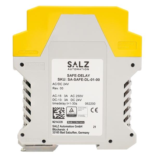
SAFE-DELAY is a safety relay with non-delayed and time-off delayed contacts for emergency stop, safety door and light curtain monitoring up to SIL 3 and Cat. 4, PL e in accordance with EN 62061 and EN ISO 13849, certified by TÜV Rheinland, 1- or 2-channel operation with or without cross circuit detection, automatic and manual start, 2 non-delayed safe relay contacts, 2 safe contacts with adjustable time delay up to 30 sec., nominal input voltage: 24 V AC/DC, max. switching capacity 250 V AC / 6 A, pluggable screw terminal blocks

Parameter Specification
In compliance with EN 60204 - 1; EN ISO 13849 - 1; IEC 62061
Operating voltage AC/DC 24 V +/- 10 %
Power consumption AC 5.3 VA/DC 4.7 W
Rated supply frequency 50 - 60 Hz
Control voltage at S11 DC 24 V
Control current typical 190 mA
Safety contacts non - delayed 2 NO
Safety contacts delayed 2 NO
Max. switching voltage AC 250 V
Contact rating of safety contacts 6 switching cycles/min AC: 250 V, 2000 VA, 8 A for resistive load
 
250 V, 3 A for AC - 15
 
DC: 40 V, 320 W, 8 A for resistive load
 
24 V, 3 A for DC - 13
Max. total current through all contacts 15 A l more than one device is closely spaced under load, the max. total current at the ambient temperature of T = 20 °C: 9 A; at T = 30 °C: 3 A; at T = 40 °C = 1 A. Otherwise a distance of 5 mm between two devices is necessary.
Minimum contact load 5 V, 10 mA
External fuses 10 A gG
Max. switch - on delay < 30 ms
Switch - off delay (adjustable) 30 ms to 30 sec.
Recovery time < 500 ms
Max. length of control line 1000 m at 0.75 mm²
Wire width 0.14 - 2.5 mm²
Tightening moment (Min./Max.) 0.5 Nm/0.6 Nm
Contact material AgSnO₂
Service Life mech. approx. 1×10⁷
Test voltage 2.5 kV (control voltage/contacts)
Rated impulse withstand voltage, leakage path/air gap 4 kV (DIN VDE 0110 - 1)
Rated insulation voltage 250 V
Degree of pollution/Overvoltage category 2/3 (DIN VDE 0110 - 0)
Protection IP20
Temperature range Ambient - 15 °C to + 40 °C
Temperature range Storage - 15 °C to + 85 °C
Max. altitude ≤ 2000 m (above sea level)
Weight approx. 250 g
Mounting DIN rail according to EN 60715 TH35
Know your supplier
Online store
On-time delivery rate
Response time
100.0%
≤4h
Company overview
Workplace: 1000m² Total staff: Highest Annual Export(usD): 300000000
Workplace: 1000m²
Total staff:
Highest Annual Export(usD): 300000000
Services
Business Type: Sales
Main Categories: Low Voltage Electrical Apparatus/Instrument meters/Production equipment/Tester/High Voltage Electrical Apparatus/Electrical fittings/Equipment Parts
Whole life care manager
Whole-life care management services for equipment procurement, use, maintenance, and after-sales, ensuring safe operation of electrical equipment, continuous control, and worry-free electricity consumption.
The equipment supplier has passed platform qualification certification and technical evaluation, ensuring compliance, professionalism, and reliability from the source.

Related Products

Related Knowledges

  • Faults and Handling of Single-phase Grounding in 10kV Distribution Lines
    Characteristics and Detection Devices for Single-Phase Ground Faults1. Characteristics of Single-Phase Ground FaultsCentral Alarm Signals:The warning bell rings, and the indicator lamp labeled “Ground Fault on [X] kV Bus Section [Y]” illuminates. In systems with a Petersen coil (arc suppression coil) grounding the neutral point, the “Petersen Coil Operated” indicator also lights up.Insulation Monitoring Voltmeter Indications:The voltage of the faulted phase decreases (in
    01/30/2026
  • Neutral point grounding operation mode for 110kV~220kV power grid transformers
    The arrangement of neutral point grounding operation modes for 110kV~220kV power grid transformers shall meet the insulation withstand requirements of transformer neutral points, and shall also strive to keep the zero-sequence impedance of substations basically unchanged, while ensuring that the zero-sequence comprehensive impedance at any short-circuit point in the system does not exceed three times the positive-sequence comprehensive impedance.For 220kV and 110kV transformers in new constructi
    01/29/2026
  • Why Do Substations Use Stones, Gravel, Pebbles, and Crushed Rock?
    Why Do Substations Use Stones, Gravel, Pebbles, and Crushed Rock?In substations, equipment such as power and distribution transformers, transmission lines, voltage transformers, current transformers, and disconnect switches all require grounding. Beyond grounding, we will now explore in depth why gravel and crushed stone are commonly used in substations. Though they appear ordinary, these stones play a critical safety and functional role.In substation grounding design—especially when multiple gr
    01/29/2026
  • Why Must a Transformer Core Be Grounded at Only One Point? Isn't Multi-Point Grounding More Reliable?
    Why Does the Transformer Core Need to Be Grounded?During operation, the transformer core, along with the metal structures, parts, and components that fix the core and windings, are all situated in a strong electric field. Under the influence of this electric field, they acquire a relatively high potential with respect to ground. If the core is not grounded, a potential difference will exist between the core and the grounded clamping structures and tank, which may lead to intermittent discharge.I
    01/29/2026
  • Understanding Transformer Neutral Grounding
    I. What is a Neutral Point?In transformers and generators, the neutral point is a specific point in the winding where the absolute voltage between this point and each external terminal is equal. In the diagram below, pointOrepresents the neutral point.II. Why Does the Neutral Point Need Grounding?The electrical connection method between the neutral point and earth in a three-phase AC power system is called theneutral grounding method. This grounding method directly affects:The safety, reliabilit
    01/29/2026
  • What’s the Difference Between Rectifier Transformers and Power Transformers?
    What is a Rectifier Transformer?"Power conversion" is a general term encompassing rectification, inversion, and frequency conversion, with rectification being the most widely used among them. Rectifier equipment converts input AC power into DC output through rectification and filtering. A rectifier transformer serves as the power supply transformer for such rectifier equipment. In industrial applications, most DC power supplies are obtained by combining a rectifier transformer with rectifier equ
    01/29/2026
Haven't found the right supplier yet? Let matching verified suppliers find you. Get Quotation Now
Haven't found the right supplier yet? Let matching verified suppliers find you.
Get Quotation Now
Send inquiry
+86
Click to upload file
Download
Get the IEE Business Application
Use the IEE-Business app to find equipment, obtain solutions, connect with experts, and participate in industry collaboration anytime, anywhere—fully supporting the development of your power projects and business.