• Product
  • Suppliers
  • Manufacturers
  • Solutions
  • Free tools
  • Knowledges
  • Experts
  • Communities
Search


Yekên Jiyayî: IEE-Business vs IEC Vacuum Circuit Breakers

Noah
Noah
qalab: Dizajin & Baxtinîve
Australia

Differences Between Vacuum Circuit Breakers Complying with IEEE C37.04 and IEC/GB Standards

Vacuum circuit breakers designed to meet the North American IEEE C37.04 standard exhibit several key design and functional differences compared to those conforming to IEC/GB standards. These differences primarily stem from safety, serviceability, and system integration requirements in North American switchgear practices.

1. Trip-Free Mechanism (Anti-Pumping Function)

The "trip-free" mechanism—functionally equivalent to an anti-pumping feature—ensures that if a mechanical trip (trip-free) signal is applied and maintained before any closing command (electrical or manual), the breaker must not close, even momentarily.

  • Once a trip signal is initiated, the moving contacts must return to and remain in the fully open position, regardless of continued closing commands.

  • This mechanism may require the release of stored spring energy during operation.

  • However, contact movement during this process must not reduce the contact gap by more than 10%, nor compromise the dielectric withstand capability of the gap. Contacts must remain in a fully isolated, open state.

  • Both electrical and mechanical interlocks must prevent closing under these conditions.

Implementation Methods:

  • Electrical Interlock: A solenoid prevents closing. When the trip button (manual or electrical) is pressed, Microswitch 1 (shown in Fig. 2) de-energizes the closing coil. Simultaneously, the solenoid plunger extends to mechanically block the closing button. Additionally, Microswitch 2 closes, inserting its normally open contact in series with the closing coil circuit, preventing electrical closing.

  • Alternative Mechanical Design: The closing button may be pressed, but the stored energy in the spring is released into the air (i.e., no load), rather than being transmitted to the main shaft to close the vacuum interrupter. This ensures safety while allowing mechanical actuation without actual closure.

2. Automatic Spring Discharge (ASD)

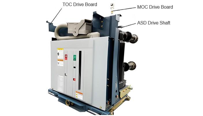
ASD (Auto Spring Discharge) is a critical safety requirement under IEEE standards. It mandates that the circuit breaker must not be in a charged (spring-energized) state when being racked in or out of its compartment—whether moving from test to service position, or being withdrawn from or inserted into the switchgear cubicle.

  • This prevents personnel from being exposed to high-energy spring mechanisms during handling, eliminating the risk of accidental energy release.

  • Therefore, the breaker must be open and uncharged before racking operations can begin.

  • A dedicated automatic energy release mechanism must be incorporated to safely discharge the stored spring energy during or prior to withdrawal from the connected position.

  • If energy is released before removal, an additional electrical interlock must prevent automatic re-energization of the spring, ensuring the breaker remains safe during maintenance.

This feature enhances personnel safety and aligns with North American safety protocols for metal-clad switchgear.

IEEE.jpg

3. MOC – Main Contacts Position Indicator (C37.20.2-7.3.6)

Unlike IEC/GB breakers, where auxiliary switches (e.g., S5/S6) indicating main contact position are typically mounted inside the breaker’s operating mechanism enclosure and directly driven by the main shaft via a linkage (simple and reliable), IEEE standards require that the Main-Open/Main-Closed (MOC) auxiliary switches be mounted inside the fixed switchgear compartment, not on the breaker itself.

Purpose of This Requirement:

  • Enable Secondary System Testing Without the Breaker: Allows technicians to simulate breaker position (open/closed) using a test probe or simulator, enabling verification of protection relays, control circuits, and signaling systems—even when the breaker is removed from the cubicle.

  • Support High-Current Auxiliary Circuits: Older control systems sometimes required high-current signaling (e.g., >5A), which standard secondary plug contacts (typically rated for 1.5 mm² wire) cannot reliably carry. Fixed MOC switches allow for heavier gauge wiring within the compartment.

Design Challenges:

  • The breaker’s main shaft must drive the fixed MOC switch in both test and service positions.

  • A drive linkage (top, bottom, or side-mounted) must transfer motion from the moving breaker to the stationary switch.

  • This requires a movable coupling rather than a rigid connection, increasing mechanical complexity.

  • Due to high impact forces during operation and potential alignment tolerances, reliability and mechanical endurance are critical.

  • IEEE requires a minimum of 500 mechanical operations for MOC mechanisms, but in practice, they must match the breaker’s full mechanical life (often 10,000 operations).

  • The added linkage mass can affect closing and especially opening speed, so lightweight, low-inertia components are essential to minimize performance impact.

4. TOC – Test and Connected Position Indicator (C37.20.2-7.3.6)

In contrast to IEC/GB breakers, where position indicators (e.g., S8/S9) are usually mounted on the breaker’s chassis and driven by the racking screw, IEEE standards require that the Test and Connected (TOC) position switches be fixed within the switchgear compartment.

  • These switches detect and signal the physical position of the breaker truck: whether it is in the Connected (Service), Test, or Disconnected (Withdrawn) position.

  • Being fixed in the compartment ensures consistent, reliable indication independent of the breaker’s internal condition.

  • This supports safe interlocking (e.g., preventing closing when not fully connected) and enables remote monitoring of breaker position.

5. Mechanical Contact Wear Indicator for Vacuum Interrupters

Unlike SF₆ circuit breakers, vacuum interrupters are sealed units with face-to-face contacts and no arcing horns or pre-insertion contacts. Both interrupting fault currents and normal mechanical operations cause contact erosion and wear.

  • Contact wear is the primary determinant of a vacuum breaker’s electrical life.

  • While many algorithms estimate electrical life based on number of operations, short-circuit current levels, and arcing time, these are largely theoretical or empirical.

  • Due to variations in first-pole-to-clear, current phase, and individual unit differences, predicted life often does not correlate precisely with actual physical wear.

  • There remains a gap between software-based predictions and real-world physical degradation.

Therefore, the North American market demands a mechanical contact wear indicator directly integrated into the vacuum interrupter or operating mechanism.

  • This visual or mechanical gauge allows maintenance personnel to directly observe the degree of contact wear during inspection.

  • It provides a reliable, physical measurement of remaining contact life, enhancing predictive maintenance and ensuring timely replacement before failure.


Bexşişek bidin û nuşkarê wê bikevin!​
Pêşniyariyek
Kewlîdarên 10kV Vacûmê Paşê Wekheş Bikeşin
I. Daxwazina Vakûm Karkerên Rezimî1. Daxwazina di Rewşa Berdest (ON) Sistema daxwaza divê di rewşa berdest be; Dereka sernavê ya herêmî divê ji dempera nîşastê re hatiye; Pêlka vekirina divê di rewşa taybetkirinê (berdestkirinê) be; Dirêja çapkanê ya karkerê ya vakûm ê di vir tiştê tablaya derînê de bi hêviyekî 4-5 mm dikare were; Tepsiya navendî di nav karkerê ya vakûm de dikare were pîkandin (ew ne li ser karkerên navendî çamîrînê werdigire); Çapkanên nîşanbendina derexa di tablaya ser û pêş d
Felix Spark
10/18/2025
چۆن دەبێت ڕێکخستەی بەرەکەرەکانی خالی دروست بەجێبە؟
01 PêşnûmaDi sistemên bixwazî de, çalakbendên cihêrên xebitand ên parzûmên herî serpilindir hene. Çalakbendên cihêrên vaku û di pazarê yên navendî de demirandin. Buna, hilberên elektrîkê dêjîn nebez peyda kirina rastîn çalakbendên cihêrên vaku. Di vê bendê de, bi rêya ku ji kerema xwe çalakbendên cihêrên vaku hilbijêrin û anîwaranên çalakbendên cihêrên vaku bibînin.02 Hêza Xebitandina Berdewamê Nabeji Herî Bilind BeHêza xebitandina berdewamê ya çalakbend nabeji herî bilind be, lê divê hêza yekê
James
10/18/2025
Vacuum vs Air Circuit Breakers: Key Differences
Vacuum vs Air Circuit Breakers: Jiyane Dîferensiyên Sereke
Vacuum vs Air Circuit Breakers: Key Differences Vacuum vs Air Circuit Breakers: Jiyane Dîferensiyên Sereke
Kurdkirên Cihêrî yên Vîlber vê Kurdkirên Vakûm: Struktur, Performans û SerkeftinKurdkirên cihêrî yên vîlber, di nav de jî hêsan kurdkirên serkeftîn û pêkhatên formkir (MCCBs), ji bo bêrkên AC da 380/690V û bêrkên DC derbas 1500V, bi amperên destnîşan ku nivîsandin 400A derbas 6300A an hatî 7500A. Ev kurdkirên vîlê bêtirbûn dikarin bikar bînin. Bêtirbûna têne xweyên dilandirina, parçkirina û yekirina bêtirê lê zêde bike (arc runner). Ev kurdkirên dikarin bêtirên kurtkirina 50kA, 80kA, 100kA, an h
Garca
10/18/2025
Davçan Çerçevekaniyan ji bo Gihazkirina Banka Pêşbazûeyan
Guhêrbarîna Nîrvanê ve Têkiliyekarina Kapasitorên di Sisteman deGuhêrbarîna nîrvanê yekemîn rêzik e ku dibeke xweşdanekirinê ya berhemên werzebûnê, kêm kirina zêdetirên şebêkeyan û serhildana stabîlîtîya sisteman.Barkirên Bêserdar di Sisteman de (Cûrekan Impedans): Ters Induktiv reaktans Kapasitiv reaktansDerêjê Tirandazî yên Daxistin da KapasitoreDi operasyonan sisteman de, kapasitoran têkil in hêsan dikeve ku faktorê guherbarî biguhezine. Di dema derêjê têkiliyê de, derêjê tirandazî mezin dibi
Oliver Watts
10/18/2025
Malperên Deyalî
Pêşnîyar bişînin​
Daxistin
IEE-Business Zêdekirin Bîzînin Wekandin
Bi karanîna sepanê IEE-Business, li her der û her dem amûr bibînin, çareseriyan bistînin, bi pîsporan re têkiliyê ava bikin, û beşdarî hevkariya pîşesaziyê bibin — ev hemû ji pêşveçûna projeyên hêz û karsaziya we re piştgirîyeke tev e.​