1. The Role of Winding in Transformer Manufacturing
The winding (coil) is the electrical circuit of the transformer and, together with the core, forms the core components. Whether a transformer operates safely, reliably, and efficiently depends to a large extent on the quality of its windings. Winding quality affects not only electrical performance such as impedance, losses, and temperature rise, but also directly determines insulation life and short-circuit withstand capability.
Winding is the central operation in coil manufacturing. It is by no means simply "wrapping several turns of wire" — it is a precise manufacturing process involving conductor selection, insulation structure, winding tension, transposition, pressing, drying, and more. For different voltage levels, capacities, and structures, engineering has developed several distinct winding forms and processes.
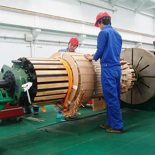
2. Basic Composition and Classification of Windings
2.1 Composition of a Winding
A transformer winding consists of the following basic elements:
| Element |
Function |
| Conductor (magnet wire) |
Carries current; commonly enamelled round wire, paper-wrapped rectangular wire, or transposed conductor |
| Insulation cylinder (former) |
Provides insulation and mechanical support between the winding and the core or adjacent winding |
| Layer/turn insulation |
Isolates adjacent conductors to ensure voltage withstand |
| Spacers, blocks, ducts |
Form cooling oil ducts while maintaining winding cross-section shape |
| Tap leads |
Lead out the tap-changing taps |
| End insulation (end rings) |
Reinforces end insulation strength |
2.2 Classification of Windings by Structure
In engineering, transformer windings are mainly divided into two broad categories:
- Layer (cylindrical) winding: The conductor is wound layer by layer in the radial direction, with layers separated by insulation. Structurally simple, used mainly for small- and medium-capacity transformers.
- Disc (pancake) winding: The winding is divided along the axial direction into several "discs" (pancakes), each consisting of a number of turns. Discs are separated by insulation spacer blocks forming ducts. Used for large-capacity, high-voltage transformers.
Disc windings are further subdivided into continuous, interleaved (interleaved-disc), inner-shielded (interleaved), helical, and foil types.
| Winding type |
Characteristics |
Typical applications |
| Cylindrical (layer) |
Simple structure, good mechanical strength |
HV/LV windings of small- and medium-capacity transformers |
| Continuous |
No solder joints, high mechanical strength, good anti-short-circuit |
Medium-/HV windings of large-capacity transformers |
| Interleaved |
Improves impulse voltage distribution, high insulation strength |
HV windings of 110 kV and above |
| Inner-shielded |
Uses insulation inserts to improve impulse distribution |
HV windings of ultra-HV transformers |
| Helical |
Good cooling, high mechanical strength |
LV windings of large-capacity transformers |
| Foil |
Suitable for automation, good manufacturability |
Dry-type and small/medium-capacity LV windings |
3. Preparation Before Winding
Winding is never "just wrap the wire"; the previous preparation determines the quality of the result.
3.1 Conductor and Insulation Material Inspection
- Conductor:
- Check the material (standard electrolytic copper), resistivity (copper ≤ 0.017241 Ω·mm²/m at 20°C), and diameter/size tolerance.
- Check the thickness, uniformity, and dielectric strength of the insulation (varnish film or paper wrapping). For paper-wrapped wire, check that the paper tape is tightly applied and free of damage.
- Check the conductor surface for burrs, scratches, oxidation, and missing insulation — conductor defects are the biggest cause of turn-to-turn short circuits.
- Insulation materials:
- Insulation paper, pressboard, cylinders, and spacers must be checked for dielectric strength, mechanical strength, and moisture content.
- Material moisture content and cleanliness must be acceptable, otherwise they affect subsequent drying and electrical strength.
3.2 Winding Machine Preparation
Winding is generally performed on a winding machine. Common types:
- Horizontal winding machine: The winding axis is horizontal, suitable for small-/medium-capacity windings and disc windings.
- Vertical winding machine: The winding axis is vertical, convenient for the segmented winding and conductor-tension control of complex continuous/interleaved windings; suitable for large high-voltage windings.
Winding machines must provide: adjustable spindle speed, constant tension control, automatic turn counting, return/rewind, pressing devices, and auxiliary welding/wrapping stations.
3.3 Importance of Tension Control
During winding, the conductor must be subjected to constant, appropriate tension:
- Tension too low: The coil is loose and oversized, with insufficient mechanical strength; it is prone to deformation or displacement during operation, and has poor short-circuit withstand ability.
- Tension too high: The conductor is stretched, its cross-section reduced, DC resistance increased, and losses rise; insulation may also be damaged.
- Tension fluctuationscause uneven tightness between turns and an elliptical coil.
Modern winding machines therefore use constant-tension pay-off devices (e.g., tension bars, magnetic-powder brakes), with tension specifications set according to conductor cross-section and material.
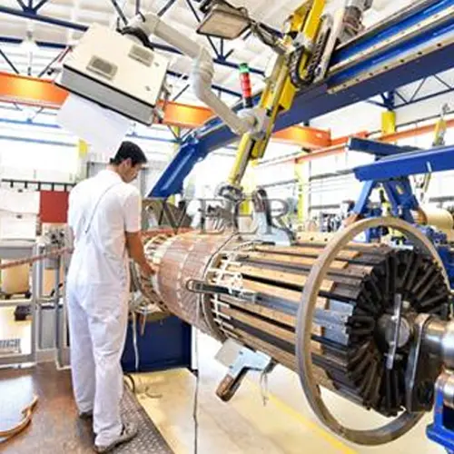
4. Layer (Cylindrical) Winding Process
This is the most basic and widely used method.
4.1 Winding Steps
- Mount the insulation cylinder: Fit the designed insulation cylinder (or paper cylinder) onto the winding former/mandrel. If the winding is to be directly slipped over the core limb, it can be wound directly on the core insulation.
- Pay off the wire: Lead the wire from the payoff spool through the tension device and guide rollers to the winding position. The conductor must be smooth and free of twisting.
- Winding: Start the winding machine (manual or automatic) and wind layer by layer according to the designed number of turns. After each layer, place layer insulation(e.g., cable paper, pressboard) and insert spacers/duct blocks(to form axial or radial ducts).
- Turn control: Use the counter to precisely control the number of turns per layer and total turns. Error must meet design requirements (typically 0 to +1 turns).
- End treatment: Reinforce insulation at the start and finish of each layer, and place end rings at both winding ends.
- Tap leads: If the winding requires tap changing, lead out tap leads at the corresponding turns and wrap them with proper insulation.
- Pressing and shaping: After winding, shape(correct ovality, expand), press(axial compression), and pre-dry the winding so its dimensions and tightness meet requirements.
4.2 Key Control Points
- Layer insulation must not be misaligned or folded.
- Turn-to-turn tightness must be uniform; the winding surface must be flat and free of bulges.
- Conductors must not cross-wind between layers.
- The position, quantity, and thickness of spacers must match the duct design.
5. Continuous Winding Process
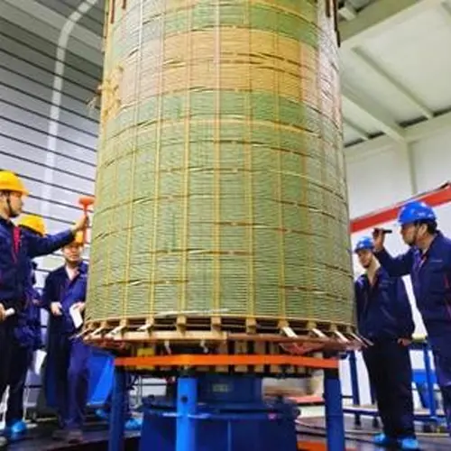
The continuous winding is the representative disc winding. The entire winding is wound continuously from a single conductor (or parallel conductors), with no solder joints between discs, giving it extremely high mechanical strength and short-circuit withstand capacity. It is the first choice for medium-voltage windings of large and medium transformers.
5.1 Structural Features
A continuous winding is divided along the axial direction into multiple "discs" (pancakes), each composed of a certain number of turns. Discs are connected by a special "crossing-wire" technique. Because transposed (crossed) connections are used, the number of turns per disc can differ, flexibly adjusting the potential distribution along the winding.
5.2 Winding Essentials
- Former and insulation cylinder: Similar to layer winding, but pads must be pre-positioned at the disc segmentation locations.
- Disc-by-disc winding: Wrap the conductor into disc after disc on the winding machine. After each disc, place insulation blocks(end insulation blocks) between discs; radial ducts form between the blocks.
- Cross-disc (transposition) connection: Connect discs via crossing wires (solder joints)or a special "flipping" operation. Key processes:
- Transposition (crossing): Adjacent disc conductors cross at the connection to balance resistance and reactance among parallel conductors, reducing circulating-current losses.
- Welding: Where welding is necessary, the joint must be strong, low-resistance, reliably insulated, and located away from stress-concentrated positions.
- Turn and segment control: Use the counter to precisely control the number of turns per disc, ensuring total turns and per-segment turns match the drawing.
- Hydraulic pressing: Use hydraulic equipment to axially press the winding, making discs compact and height-consistent.
- Pressing and drying: Finally shape, pre-dry, and press.
5.3 Advantages and Difficulties
- Advantages: no solder joints, high mechanical strength, strong short-circuit withstand, flexible cooling-duct layout.
- Difficulties: complex process, high demands on operators and automation equipment, strict insulation handling at transposition and crossing locations.
6. Interleaved Winding Process
6.1 Why "Interleaving"
When the transformer is hit by overvoltage (especially lightning impulse), the initial impulse voltage distribution over the winding turns is not uniform. The turn-to-turn potential gradient near the line end is very large, easily causing turn-to-turn breakdown. Thus the interleaved winding appeared.
6.2 Principle and Structure
Through a special "interleaving" connection, the interleaved winding makes turns that are electrically series-adjacent not spatially adjacent, but "spaced apart." This equalizes the impulse voltage gradient through capacitance (increasing longitudinal capacitance and improving potential distribution), significantly raising the winding's ability to withstand impulse voltage.
6.3 Winding Characteristics
The difficulty of interleaved winding lies in its "non-sequential, non-adjacent" continuous method:
- The conductor is wound in an alternating "forward — backward — forward" pattern; after winding a group, it skips over several turns and winds the next group, forming the interleaved structure.
- Because the conductor repeatedly crosses over and transposes, tension control and insulation wrapping are extremely demanding; insulation damage and transposition errors are prone to occur.
- Vertical winding machinesare often used, with automatic error correction and simulation control, assisted by fixtures (winding jigs)to ensure position accuracy.
- The number of turns and interleaving times per disc must strictly follow the design; otherwise the impulse potential distribution is destroyed.
Interleaved windings are typically used for HV windings of 110 kV and above, often combined with continuous windings (e.g., end-interleaved, inner-shielded).
7. Inner-Shielded (Interleaved-Inserted) Winding Process
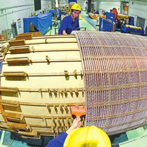
The inner-shielded winding (also known as "interleaved-inserted") is a structure developed from continuous or interleaved windings, commonly used for ultra-HV and extra-HV (e.g., 500 kV, 750 kV, 1000 kV) HV windings.
- Its feature is the insertion of shield conductors (floating shield segments)inside the winding. The capacitance effect of the shield conductors further equalizes the impulse voltage distribution.
- During winding, shield conductors must be inserted at the designated turn/segment positions and fixed with insulation parts.
- Extremely high demands are placed on the insulation wrapping, fixing position, and end treatment of the shield conductors. The winding process is complex and typically uses vertical CNC winding machines with simulation verification.
8. Helical Winding Process
Helical windings are mainly used for LV windings of large-capacity transformers. Each turn of the conductor spirals down the winding axis (like a screw thread); inter-turn insulation and spacer blocks form radial or axial ducts.
8.1 Winding Essentials
- Multiple parallel conductors: Large-current LV windings often use multiple parallel conductors. Correct transpositionmust be performed during winding (conductors are crossed and transposed at the corners) to balance the current among parallel branches and avoid circulating-current losses.
- Helical pitch control: Control the helix angle and pitch to keep each turn position accurate and uniform.
- Cooling ducts: Set spacer ducts reasonably between turns to ensure smooth flow of cooling oil.
- Pressing and shaping: After winding, axially press the winding to keep it neat and compact.
8.2 Characteristics
- Good cooling performance, suited to large currents.
- Good mechanical strength.
- Transposition is the difficult point; improper handling causes local overheating.
9. Foil Winding Process
Foil windings use copper (or aluminum) foil strips instead of round/rectangular wire, mainly used for dry-type transformers and small-/medium-capacity LV windings, also seen in oil-immersed transformers.
- The foil strip is wound continuously, with layers separated by insulation film (e.g., polyester film, Nomex).
- Advantages: suitable for automated production, high production efficiency, uniform layer-to-layer voltage distribution, good anti-short-circuit and cooling performance.
- Winding essentials: strict control of foil tension and alignment; reliable connection of end busbars (copper bars) to the foil (welding or crimping); layer insulation film must be fully covered, free of bubbles and skewing.
10. Post-Winding Treatment and Quality Control
10.1 Pressing and Shaping
The wound winding is not used directly. It must undergo:
- Shaping: Correct ovality and axial dimensions on a shaping machine to restore the design profile.
- Pre-drying: Remove moisture from wire and insulation materials to prevent insulation dampness after tanking.
- Axial pressing: Apply the design-specified axial pressure on a press or hydraulic device to compact the winding, bring dimensions to spec, and meet anti-short-circuit mechanical strength requirements.
10.2 Key Electrical Tests
After winding, the following inspections are usually performed:
- DC resistance measurement: verifies that turns, connections, and transpositions are correct and parallel branches are balanced.
- Turn-to-turn / layer dielectric test: verifies that turn/layer insulation was not damaged during winding.
- Induced voltage and impulse tests(at the active-part or complete-unit stage): verifies that the insulation structure can withstand working and overvoltages.
- Dimensional and cosmetic inspection: winding diameter, height, ducts, and insulation condition match the drawing.
10.3 Common Winding Defects and Their Effects
| Defect |
Consequence |
| Turn insulation damage / missing varnish |
Turn-to-turn short circuit, local overheating, burnout |
| Conductor cross-section stretched thin |
Higher resistance losses, higher temperature rise |
| Loose / elliptical coil |
Poor mechanical strength, weak anti-short-circuit, noise |
| Improper transposition / crossed conductors |
Higher circulating-current losses, local overheating |
| Misaligned / damaged layer insulation |
Layer-to-layer breakdown |
| Poor tap connection |
High contact resistance, local overheating |
11. Conclusion
Transformer winding is a technically dense process. From conductor selection and insulation structure design, to tension control, transposition, segmented winding, and pressing/shaping, every step targets electrical performance, insulation life, and mechanical strength. Different capacities and voltage levels select different winding forms: small-/medium-capacity units mostly use layer/continuous windings; large-capacity HV units mostly use interleaved, helical, or inner-shielded windings; automation and intelligence promote foil windings and CNC winding equipment.
Understanding the winding process is not only a prerequisite for transformer manufacturing, but also an important basis for judging transformer quality and diagnosing operating faults (such as partial discharge and circulating-current overheating).
Contact us:
Edited From:Dyson

 Login
Login