Search


Transformer Operation and Maintenance Technical Analysis Report: Root Cause Analysis of Transformer Burn-out Due to Oil Loss in Madagascar

Technical analysis report on transformer burn-out due to oil loss in Madagascar: root causes, failure mechanisms, and prevention strategies.

Noah
Field: Design & Maintenance
10Year<
Australia
Add us on Google

1. Incident Background

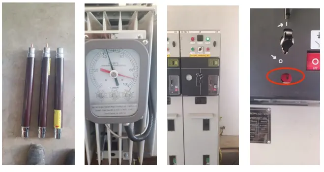
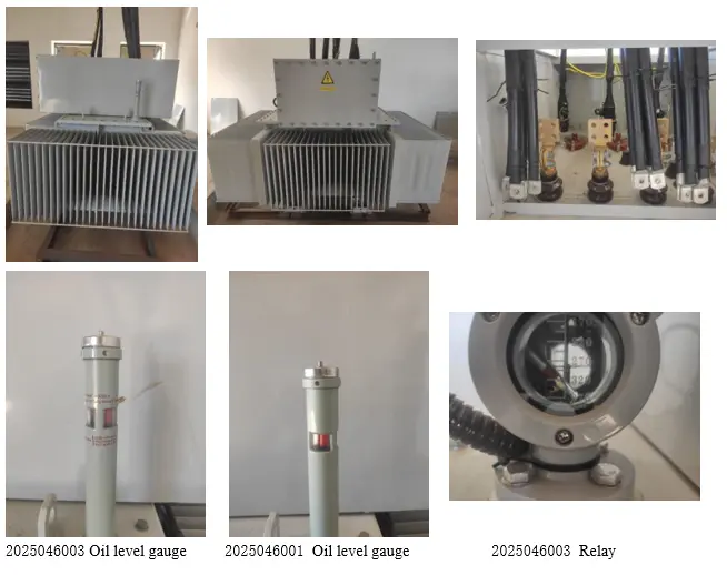
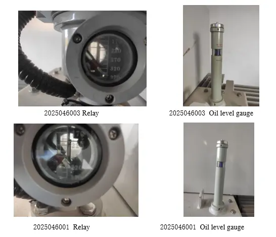
On April 25, 2026, the customer reported that after a local grid power outage and restoration, a QM unit in an SM66 cabinet failed to activate, and two internal fuse tubes were blown. Subsequent inspection revealed red oil level alarms on both Transformer 1 and Transformer 2, along with relay abnormalities. After venting, testing, and disassembly, it was confirmed that Transformer 1 was damaged due to oil loss causing switch burn-out, while Transformer 2 remained operational.

Transformer Operation and Maintenance Technical Analysis Report: Root Cause Analysis of Transformer Burn-out Due to Oil Loss in Madagascar

2. Fault Timeline (Based on Field Records)

  • April 25: QM unit failed to activate after grid restoration; two fuse tubes blown.
  • April 27: Oil level indicators on both transformers showed red; relays suspected faulty.

Transformer Operation and Maintenance Technical Analysis Report: Root Cause Analysis of Transformer Burn-out Due to Oil Loss in Madagascar

  • April 28: After venting the relays, oil level indicators returned to "normal."

Transformer Operation and Maintenance Technical Analysis Report: Root Cause Analysis of Transformer Burn-out Due to Oil Loss in Madagascar

  • May 3: Customer testing confirmed Transformer 2 operational; Transformer 1 had burned out.
  •  
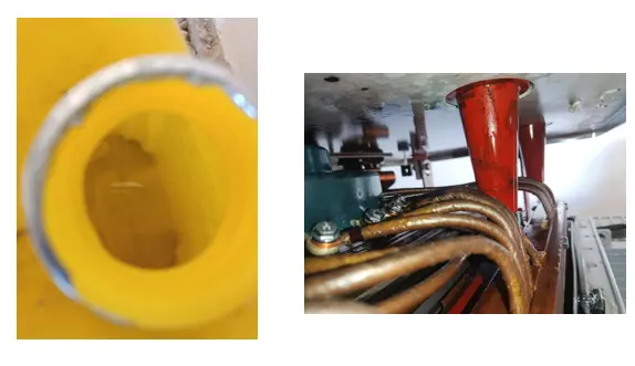
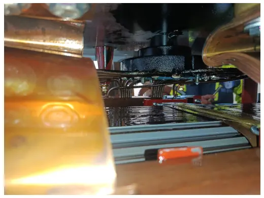
  • May 14: Disassembly revealed that oil loss in Transformer 1 caused switch burn-out; oil color normal, no leakage traces found.
  • May 16: Customer confirmed no oil leakage on site; transformers had been operating under high temperature for approximately three months; several other units also showed signs of oil loss.

3. Root Cause Analysis

3.1 Direct Cause

Oil loss reduced insulation capability. Under the overvoltage or lightning surge that occurred during grid restoration, insulation breakdown intensified, causing switch burn-out and ground fault, ultimately leading to fuse blowing and trip protection activation. Disassembly directly confirmed that oil loss caused the switch burn-out.

Transformer Operation and Maintenance Technical Analysis Report: Root Cause Analysis of Transformer Burn-out Due to Oil Loss in Madagascar

Transformer Operation and Maintenance Technical Analysis Report: Root Cause Analysis of Transformer Burn-out Due to Oil Loss in Madagascar

3.2 Cause of Oil Loss (Key Physical Mechanism)

No oil leakage was found on site, yet the oil level continued to drop. Based on operation and maintenance records, the root cause of oil loss is determined as follows:

  • Vent not properly reseated after operation: On April 28, after venting the relay, the customer did not verify whether the vent valve or relay seal was fully closed, leaving a tiny gap.
  • Breathing effect carrying oil vapor: During transformer operation, oil temperature rises, internal pressure increases, and the oil-gas mixture slowly escapes through the gap. When cooling, external air is drawn in. Each expulsion cycle carries away a small amount of oil vapor.
  • Irreversible oil level decline: Prolonged "breathing" caused continuous oil loss in vapor form. The oil level indicator had shown a false "normal" reading due to gas interference, and the customer did not perform actual oil level measurement or refilling. The oil level eventually dropped to a dangerous level.

3.3 Underlying Cause — Negligent Maintenance

  • No reseating check: After venting, the seal was not verified, and no oil refill procedure was performed.
  • No monitoring: Oil level indication was local only (pointer-type), with no remote alarm. Inspection intervals were too long, and no additional checks were scheduled during high-temperature seasons.
  • No records: Historical oil level data was absent, making it impossible to detect a slow downward trend.
  • No verification: When the oil level indicator returned to "normal," the customer mistakenly assumed the problem was resolved, without using an oil dipstick or sight glass to verify the actual oil volume.

4. Incident Chain

Venting without reseating the vent → tiny gap in seal → Breathing effect (hot: oil-gas mixture expelled; cold: air drawn in) → Continuous oil vapor loss → Slow oil level decline (no visible leakage) → Critically low oil level → Reduced insulation strength → Grid restoration / overvoltage / lightning surge → Insulation breakdown → Switch burn-out, ground fault → Fuse blowing, trip protection activation → Transformer 1 permanently damaged

5. Conclusion

  • Direct cause of Transformer 1 failure: Oil loss reduced insulation capability, leading to breakdown and burn-out under overvoltage conditions.
  • Direct cause of oil loss: Vent not reseated after venting; breathing effect caused gradual oil vapor loss over time.
  • Root cause: Negligent maintenance — operations not closed-loop (venting without reseating), monitoring absent (no contactless oil level verification, no remote alarm), and inadequate inspection and recording procedures.

6. Corrective Recommendations

6.1 Immediate Actions (for the same transformer batch)

  • Measure actual oil level on all in-service transformers (using oil dipstick or sight glass); refill to rated oil level.
  • Check sealing of all relay vent and drain valves; ensure fully closed.
  • After the oil level indicator returns to a normal reading, always use a secondary method (e.g., oil dipstick) to verify actual oil level, and record the result.

6.2 Management Measures

  • Revise maintenance procedures: After any venting or draining operation, implement a closed-loop "reset — inspect — refill — verify" process.
  • Increase inspection frequency: During high-temperature seasons (ambient temperature ≥ 35°C), shorten oil level inspection intervals to once per week.
  • Establish oil level trend records: Record actual oil level (in mm or L) at each inspection; plot change curves to detect slow declines early.
  • Install remote oil level alarms: For critical transformers or remote sites, retrofit with oil level gauges that provide low-level remote signaling (recommended only where necessary).

Prepared by: Technical Analysis Team
Reviewed by:Noah
Date: June 10, 2026

Give a tip and encourage the author!

Comments

Share your question or perspective
WhatsApp
Send inquiry
+86
Click to upload file
Download
Get the IEE Business Application
Use the IEE-Business app to find equipment, obtain solutions, connect with experts, and participate in industry collaboration anytime, anywhere—fully supporting the development of your power projects and business.
Login
or continue with
New here?
Register