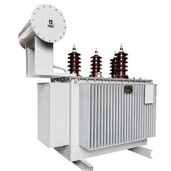
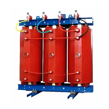
What is a Grounding Transformer?
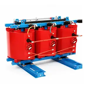
A grounding transformer (often called a "grounding bank") is designed to provide an artificial neutral point for power systems that lack one. This allows for the connection of arc suppression coils (Petersen coils) or low-resistance grounding. Its primary purpose is to limit capacitive currents during ground faults, thereby enhancing the reliability of the distribution network.
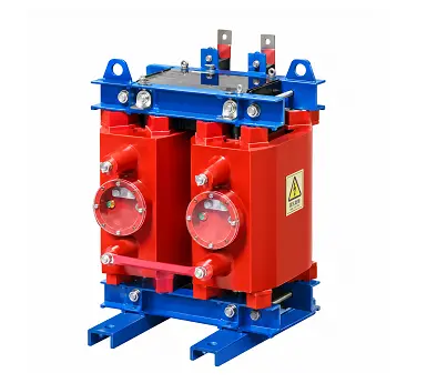
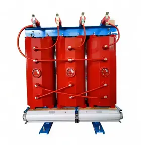
Grounding transformers are categorized by their insulation medium (oil-immersed or dry-type) and phase configuration (single-phase or three-phase).
The Challenge in Ungrounded Systems
In 6kV, 10kV, and 35kV networks, the neutral point is often ungrounded. Since the low-voltage side of main transformers is typically Delta-connected, there is no physical neutral point available for grounding.
While ungrounded systems can tolerate a single-phase ground fault for 1-2 hours, modern urban grids with extensive cabling have significantly increased capacitive currents. When these currents exceed 10A, several risks arise:
- Intermittent Arcing: This can cause overvoltages reaching up to 4 times the normal peak voltage, threatening equipment insulation.
- Resonance: It may trigger ferroresonance, potentially damaging voltage transformers and surge arresters.
- Phase-to-Phase Shorts: Arcing can ionize the surrounding air, leading to more severe short circuits.
To mitigate these risks, an artificial neutral point is required to connect compensation devices.
Global Usage and Z-Connection
- In China: Grounding transformers typically use a Zig-Zag (Z) connection. To save space and investment, a tertiary winding is often added to supply power to substation auxiliaries.
- Internationally: Z-connection transformers are also widely used in 10kV ungrounded systems. They present high impedance to positive and negative sequence currents but low impedance to zero-sequence currents, ensuring reliable ground protection operation.
Three-Phase vs. Single-Phase Units
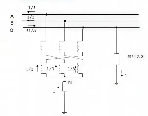
- Three-Phase (Z-Connection): Unlike standard transformers, each phase coil is split into two groups wound in opposite directions on different core legs. This allows zero-sequence flux to flow through the core legs, resulting in very low zero-sequence impedance (approx. 10Ω). Consequently, a Z-connection transformer can carry an arc suppression coil with a capacity of 90%–100% of its rating.
- Single-Phase: These are primarily used to create a neutral point for generator or transformer neutral grounding resistor cabinets, helping to reduce the size and cost of the resistor package.
Key Operating Characteristics
- Low Zero-Sequence Impedance: Ensures effective output of zero-sequence current.
- High Excitation Impedance: Minimizes no-load current.
- Low No-Load Loss: Improves energy efficiency during daily operation.
Comparison of Connection Methods
- YNyn Connection:
Uses a three-limb core. However, zero-sequence flux cannot circulate within the core and must pass through the tank and clamps, causing local overheating. Regulations strictly limit the connected arc suppression coil to 20% of the transformer's rating.
- YNd Connection:
The Delta secondary provides a path for zero-sequence currents, reducing impedance. However, it is difficult to supply mixed lighting and power loads from a Delta winding. The capacity for the arc suppression coil is limited to 50% if the secondary is fully loaded.
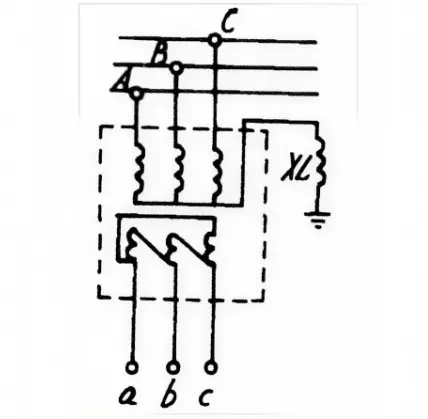
- ZNyn Connection (The Industry Standard):
This is the most common configuration globally. The Zig-Zag connection cancels out zero-sequence magnetomotive forces on the same core leg, resulting in minimal leakage flux and very low impedance.
Capacity: It can support an arc suppression coil equal to its own rating.
Auxiliary Power: The yn secondary allows for supplying local loads or station service (typically 80-200 kVA).
Design Note: Due to the vector arrangement, a Z-connection requires approximately 1.15 to 1.16 times more turns than a standard Star connection for the same voltage.
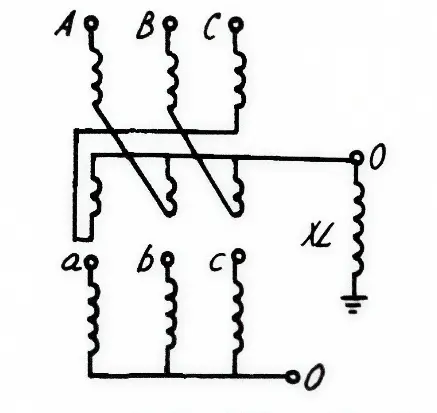
Working Principle
During a single-phase ground fault (e.g., Phase C), the fault current flows through the earth into the neutral point. It then splits equally into the three phases of the grounding transformer.
Because the currents in the two windings on the same core leg are equal and opposite, their magnetic forces cancel each other out. This results in extremely low zero-sequence impedance (typically 6-10Ω, compared to 600Ω for a Star connection). This low impedance allows the compensation current to flow freely while maintaining symmetrical line voltages, ensuring the system remains safe and stable.

 Login