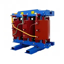
A grounding transformer is also called a neutral grounding transformer. It creates an artificial neutral point in power systems where the neutral is not directly available or is ungrounded.
It does not normally carry significant load current. Instead, it provides a reliable path for zero-sequence current during a single-phase ground fault. It works together with a neutral grounding resistor, earthing resistor, or arc suppression coil. This helps limit fault current, suppress transient overvoltages, and enable protective relaying.
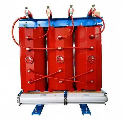
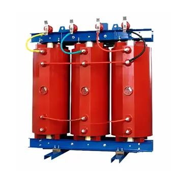
Dry-type grounding transformers are widely used in substations, switchgear rooms, data centers, hospitals, industrial plants, and renewable energy stations. They are oil-free, fire-resistant, and require relatively low maintenance.
Why Grounding Transformers Are Needed?
Many 6 kV, 10 kV, and 35 kV medium-voltage distribution networks use an ungrounded or arc-suppression-coil grounded neutral. If the low-voltage side of the main transformer is delta-connected, there is no accessible neutral point for grounding.
When a single-phase ground fault occurs, the capacitive earth fault current may become large enough to sustain an arc. This can lead to arcing ground overvoltages, ferroresonance, or even phase-to-phase faults.
A grounding transformer provides a stable artificial neutral point. The system can then be grounded through a resistor, reactor, or other earthing device. This improves both system safety and protection sensitivity.
How It Works: The Advantage of Zig-Zag Connection?
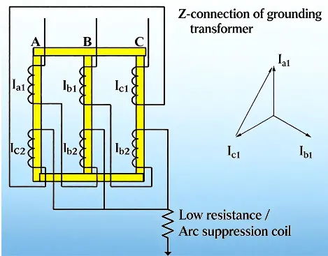
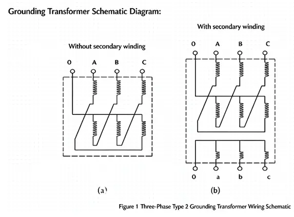
Grounding transformers commonly use a zig-zag connection. Each phase winding is divided into two parts. These parts are wound in opposite directions on different core limbs and then connected in series to bring out the neutral point.
Under normal conditions, the three-phase voltages are essentially balanced.
The grounding transformer mainly carries magnetizing current. It presents high impedance to positive- and negative-sequence currents, so it operates close to no-load.
During a single-phase ground fault, zero-sequence current flows through the neutral point to earth.
The zig-zag arrangement allows zero-sequence flux to form a closed path within the core. This results in low impedance to zero-sequence current.
Compared with conventional power transformers, a zig-zag grounding transformer has much lower zero-sequence impedance.
It is therefore better suited to carry ground fault current. The exact zero-sequence impedance depends on product capacity, core structure, and system voltage level. It should be confirmed from the manufacturer's test reports and system fault studies.
Common Types and Connection Arrangements
Grounding transformers can be classified as follows:
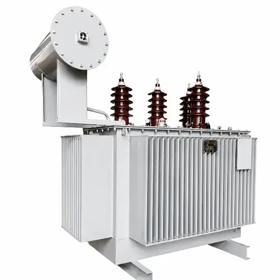
- By insulation medium: oil-immersed grounding transformers and dry-type grounding transformers.
- By phase number: three-phase and single-phase grounding transformers.
- By winding arrangement: two-winding and three-winding grounding transformers.
A three-winding grounding transformer often includes an auxiliary low-voltage winding. This winding can serve as a station service transformer. The unit then provides both an artificial neutral point and auxiliary power supply, reducing equipment count and saving space.
Typical connection arrangements include ZNyn and YNd. The final selection should be based on system voltage, grounding method, protection requirements, and any auxiliary load demand.
Key Parameters and Selection Considerations
Important parameters for selection include:
- Rated voltage: should match the system voltage, such as 10 kV or 35 kV.
- Zero-sequence impedance: affects single-phase ground fault current. It must be coordinated with the neutral grounding resistor, arc suppression coil, and protection settings.
- Rated capacity: determined by system capacitive current, grounding method, and short-time fault current.
- Insulation class: common classes for dry-type units are Class F and Class H.
- Short-time current capability: the transformer must withstand ground fault current for the required fault duration.
- Grounding method: low-resistance grounding, high-resistance grounding, reactance grounding, arc suppression coil grounding, or solid grounding.
In low-resistance grounded systems, the grounding transformer capacity must be checked against system voltage and target fault current. It must also be checked against the required fault duration. The continuous rating should be derived from the short-time thermal duty. If the unit also supplies a station service load, the auxiliary load must be added to avoid long-term overheating.
Typical Applications
- 10 kV / 35 kV distribution networks: providing an artificial neutral point and limiting arcing overvoltages.
- Cable networks: higher capacitive earth fault current requires a controlled grounding method.
- Renewable energy plants: stabilizing neutral point potential in PV and wind farm collection systems.
- Data centers, hospitals, and industrial facilities: improving grounding safety and fault detection.
- Substation auxiliary supply: using a three-winding grounding transformer as a station service transformer.
Daily Inspection Checklist
A dry-type grounding transformer normally operates at no-load or very light load. It only carries significant current during a ground fault. Routine inspections should cover both general dry-type transformer items and the neutral earthing circuit.
| Inspection Area |
Key Items |
Normal Condition / Action |
| Appearance and insulation |
Enclosure, windings, insulators, bushings, core clamps |
No cracks, discoloration, carbonization, tracking, or foreign material; clean accumulated dust during outage |
| Electrical connections |
Cable terminations, busbars, terminals, bolts |
No looseness, oxidation, discoloration, or burning; check with infrared thermography |
| Neutral and earthing |
Neutral lead, earthing resistor or arc suppression coil, enclosure earthing, core earthing |
Earthing conductors secure and free from corrosion; protective earthing resistance typically ≤ 4 Ω or as required by the earthing grid; neutral earthing resistance must be determined by system calculation |
| Temperature and cooling |
Temperature controller, winding temperature, cooling fans, air ducts |
Class F units commonly alarm around 130 °C and trip around 150 °C; Class H allows higher temperatures; confirm settings with nameplate and manufacturer data |
| Sound and vibration |
Core, clamps, enclosure, fans |
Uniform humming is normal; investigate cracking, arcing, or metallic noise immediately |
| Operating parameters |
Voltage, current, phase balance, zero-sequence current |
Voltage deviation preferably within ±5 %; balanced phase currents; abnormal zero-sequence current requires investigation |
| Environment |
Ventilation, temperature, humidity, condensation, pest protection |
Ambient temperature generally ≤ 40 °C; relative humidity ≤ 85 %; no condensation, debris, or damaged sealing |
Common Faults and Troubleshooting
| Symptom |
Possible Cause |
Recommended Action |
| Neutral point voltage shift |
Phase unbalance, poor earthing, system ground fault |
Check load balance, earthing circuit, and zero-sequence voltage |
| Abnormal zero-sequence current |
Single-phase ground fault, earthing resistor fault, protection issue |
Verify system fault condition; inspect neutral circuit, earthing resistor, and zero-sequence CT |
| Overheating windings or joints |
Loose connection, overload, fan failure |
Perform infrared inspection; tighten connections; check fans and air ducts |
| Discharge noise or odor |
Moisture, dust accumulation, partial discharge |
Inspect insulation surface during outage; carry out insulation tests if required |
| High core earthing current |
Multiple core earthing points, insulation aging |
Measure core insulation resistance; locate and remove unintended earthing points |
| Zero-sequence protection trip |
Actual ground fault, earthing resistor damage, CT or relay malfunction |
Confirm whether a genuine fault occurred; inspect neutral circuit, earthing resistor, zero-sequence CT, and relay settings |
Maintenance and Testing Recommendations
Maintain operating records for winding temperature, current, voltage, zero-sequence current, and fan operation. Monthly activities may include visual inspection, terminal tightening, and fan function tests. Quarterly checks should cover the earthing system, core earthing current, and insulation condition.
Annual or code-based testing may include insulation resistance, winding DC resistance, turns ratio, temperature controller calibration, and partial discharge testing where applicable.
Although a grounding transformer carries very little load during normal operation, its reliability directly affects ground fault protection performance. The neutral lead, earthing resistor, arc suppression coil, and zero-sequence protection circuit should be treated as priority inspection points.
Scope and Safety Notes
This article is intended for general reference on dry-type grounding transformers used in medium-voltage distribution systems. Specific parameters, settings, and maintenance intervals should always follow the equipment nameplate, manufacturer instructions, project specifications, and applicable local standards.
During live inspections, maintain safe clearance from energized parts. Any work involving isolation, terminal tightening, or testing must follow proper lockout/tagout, verification of de-energization, and earthing procedures.
The information provided here is for technical discussion only and does not constitute engineering design, protection coordination, or operational instruction.

 Login
Login